
Low Cost Capacitive Touch Switch II circuit schematic with explanation

The touch switch circuit designed with the CD4017 decade counter provides a versatile solution for applications requiring a touch-activated on/off mechanism. The CD4017 is a popular decade counter IC that counts from 0 to 10 and provides ten outputs (Q0 to Q9). In this configuration, the touch plate serves as the input trigger, sending a pulse to the clock input of the CD4017 every time it is touched.
When the circuit is powered, the CD4017 begins at an initial state of Q0 being high and all other outputs low. The output connected to Q1 is used to drive the load. Upon the first touch of the plate, the CD4017 increments to Q1, turning on the load. A second touch increments the counter again, resetting the output to Q0, which turns off the load. This toggle function effectively allows the user to control the load with a single touch plate, simplifying the user interface.
Additional components may be incorporated into the circuit for enhanced functionality, such as debounce circuitry to prevent false triggering due to noise or unintended touches. A capacitor can be placed in parallel with the touch plate to filter out high-frequency noise, ensuring that only deliberate touches are registered.
Furthermore, the use of a pull-down resistor at the input can help stabilize the input signal when the touch plate is not activated, preventing floating states that might lead to erratic behavior. The circuit can be powered by a standard DC voltage supply, compatible with the operating range of the CD4017, typically between 3V and 15V.
This design not only meets the requirement for a touch-activated switch but also offers a reliable and efficient method for controlling electrical loads in various applications, including lighting systems, appliances, and automated devices.In my previous post of capacitive touch switch, it gives the o/p as long as you touch it. Means it was only drive the load when you touch it, and when you remove your hand/finger then it was not able to drive the load. Tough that touch switch circuit can be used in various apps but does not meet my requirements. So by changing the circuit a little bit i am able to design a touch switch that behave like a normal switch i. e touch to on and touch to off. For this i used CD4017 decade counter. Output of 40106 drives this counter and load is connected to the pin2 of the counter, and reset is to pin4. When you touch the touch plate (wire in my case) a pulse is provided to the counter and it increments its o/p.
So as the load is connected to the Q1 of counter, the o/p is high to drive the load. Similarly if you want to switch off the load and again touch the plate; counter will increment again and reset itself and make Q0 high. As your load is not connected to this pin it will go off. That is all!. 🔗 External reference
Related Circuits
This simple circuit is the electronic version of the combination lock. Using the special purpose LS7220 digital lock IC, the circuit allows a 4 digit combination of your choice to activate a relay for a set period of time....
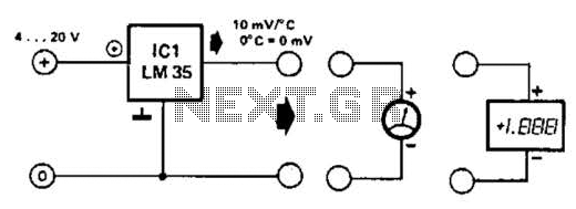
An effective temperature sensor circuit is designed to receive power from a 4-to-20 mA loop without impacting the loop current. The temperature sensor integrated circuit (IC) used is the AD590F, which operates with a supply voltage ranging from 4...
The file being accessed no longer exists. It may have been renamed or removed from the archive. Navigation links are available on the left to browse the desired area of the archive. The connection is to cdn.preterhuman.net, which mirrors...
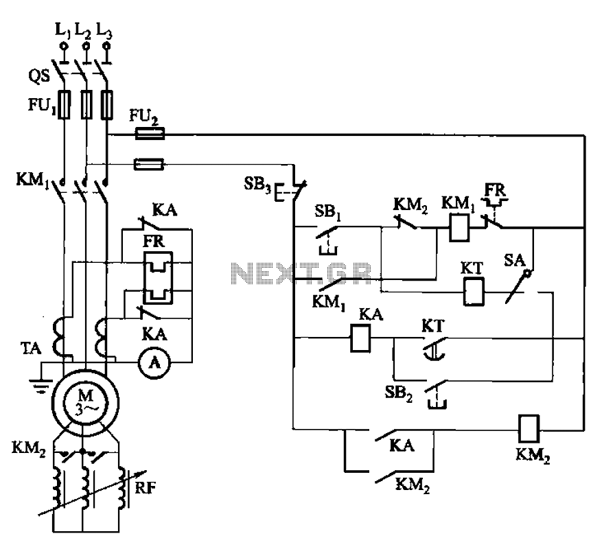
The circuit shown in Figure 3-164 can operate in both manual and automatic modes. During startup, the normally closed contact of relay KA is shorted, which affects the heating element to avoid prolonged startup times that could lead to...
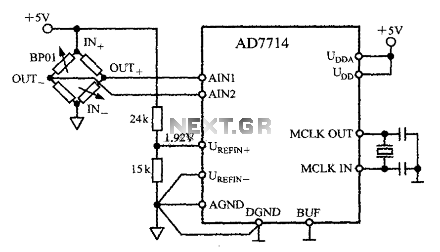
The AD7714 circuit consists of a pressure measurement system featuring the BP01 pressure sensor from Sensym. The BP01 is integrated into a bridge circuit, which produces a differential output voltage. When the sensor is subjected to its rated full-scale...
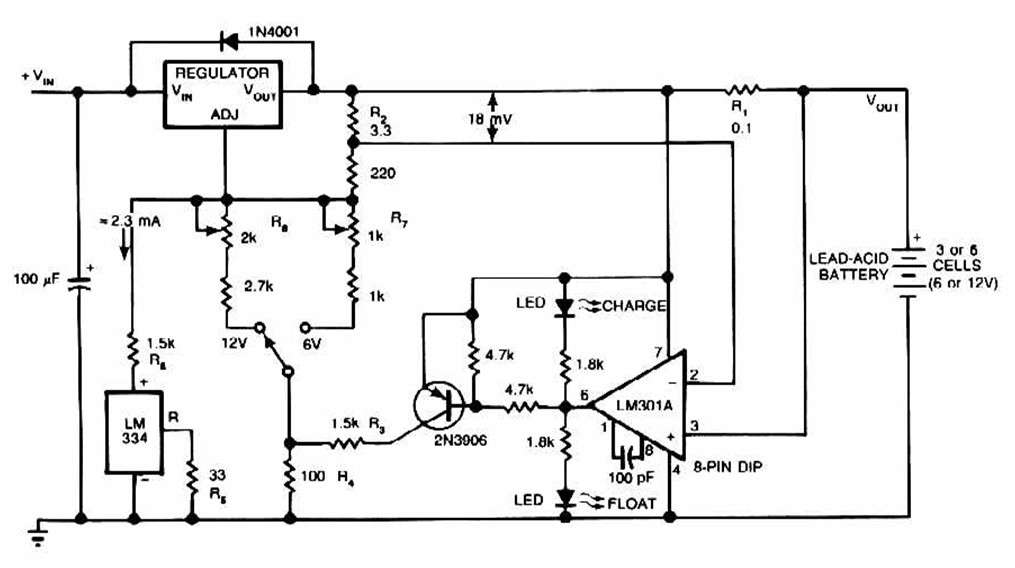
The schematic for this charger is straightforward. It is designed to charge a Gel Cell or other lead-acid types. This simple battery level monitor circuit can indicate the charging process in a 12 Volt lead-acid battery or tubular battery....