
Keypad Combination Lock circuit

C1 1 1uF 25V Electrolytic Capacitor
C2 1 220uF 25V Electrolytic Capacitor
R1 1 2.2K 1/4W Resistor
Q1 1 2N3904 NPN Transistor 2N2222
D1 1 1N4148 Rectifier Diode 1N4001-1N4007
K1 1 12V SPDT Relay Any appropriate relay with 12V coil
U1 1 LS7220 Digital Lock IC
S1-S12 12 SPST Momentary Pushbutton Keypad (see notes)
HD1 1 12 Position Header
Notes
To set the combination, wire the appropriate switches to U1 pins 3, 4, 5 and 6 using the header. For example if S1 was connected to pin 3, S2 to pin 4, S3 to pin 5 and S4 to pin 6, the combination would be 1,2,3,4. Now wire all other unused switches across the header to pin 2 of U1. In this way you can create any 4 digit combination you want. Pin 2 is the reset pin, so connecting all unused keys to it assures that the entire combination must be reentered if an incorrect key is pressed. When the appropriate combination is entered, the relay is activated for a period of time determined by C1. The 1uF capacitor specified in the parts list will result in an on-time of roughly 5 seconds. Increase the value of C1 to increase this time. An easy way to make a keypad is to buy 12 PC board mount pushbuttons and then etch a PC board so that the buttons are in 4 rows of 3, similar to a telephone keypad. Place this in a case and then use a label maker or transfer letters to add your numbers to the tops of the pushbuttons. You can also use a pre made keypad but keep in mind that you need a pad which provides an output for each key. Most pads available have the keys connected to provide a row and column signal when they are pressed.
The circuit operates as follows: Upon powering the circuit, the LS7220 Digital Lock IC (U1) awaits input from the keypad composed of 12 momentary pushbuttons (S1-S12). Each pushbutton corresponds to a digit in the combination. The configuration of the pushbuttons is crucial, as it determines the specific combination that will activate the relay (K1). The wiring of the pushbuttons to pins 3, 4, 5, and 6 of U1 allows for a flexible combination setup, while pin 2 serves as a reset point to ensure security; if any incorrect button is pressed, the user must start over.
When the correct sequence is entered, U1 activates the transistor (Q1), which in turn energizes the relay (K1) for a duration dictated by the timing capacitor (C1). The choice of a 1uF capacitor provides an approximate activation time of 5 seconds, which can be modified by using a larger capacitance to extend the relay's on-time. The relay can then control various devices, such as solenoids or motors, allowing for a wide range of applications from locking mechanisms to automated doors.
The additional capacitor (C2) may be used for stabilizing voltage levels in the circuit, ensuring reliable operation of the LS7220 and other components. The rectifier diode (D1) protects the circuit from potential back EMF generated by the relay coil, safeguarding the digital lock IC and other sensitive components. The inclusion of a header (HD1) facilitates easy connections for the keypad and additional components, streamlining the assembly process. Careful attention to the layout and connections will enhance the reliability and functionality of this combination lock circuit.This simple circuit is the electronic version of the combination lock. Using the special purpose LS7220 digital lock IC, the circuit allows a 4 digit combination of your choice to activate a relay for a set period of time. This relay can then be used to trigger a lock solenoid, enable a starter button, open a motorized door, or many other tasks that require a momentary signal.
C1 1 1uF 25V Electrolytic Capacitor C2 1 220uF 25V Electrolytic Capacitor R1 1 2.2K 1/4W Resistor Q1 1 2N3904 NPN Transistor 2N2222 D1 1 1N4148 Rectifier Diode 1N4001-1N4007 K1 1 12V SPDT Relay Any appropriate relay with 12V coil U1 1 LS7220 Digital Lock IC S1-S12 12 SPST Momentary Pushbutton Keypad (see notes) HD1 1 12 Position Header Notes To set the combination, wire the appropriate switches to U1 pins 3, 4, 5 and 6 using the header. For example if S1 was connected to pin 3, S2 to pin 4, S3 to pin 5 and S4 to pin 6, the combination would be 1,2,3,4.
Now wire all other unused switches across the header to pin 2 of U1. In this way you can create any 4 digit combination you want. Pin 2 is the reset pin, so connecting all unused keys to it assures that the entire combination must be reentered if an incorrect key is pressed. When the appropriate combination is entered, the relay is activated for a period of time determined by C1.
The 1uF capacitor specified in the parts list will result in an on-time of roughly 5 seconds. Increase the value of C1 to increase this time. An easy way to make a keypad is to buy 12 PC board mount pushbuttons and then etch a PC board so that the buttons are in 4 rows of 3, similar to a telephone keypad. Place this in a case and then use a label maker or transfer letters to add your numbers to the tops of the pushbuttons.
You can also use a pre made keypad but keep in mind that you need a pad which provides an output for each key. Most pads available have the keys connected to provide a row and column signal when they are pressed.
🔗 External reference
Related Circuits
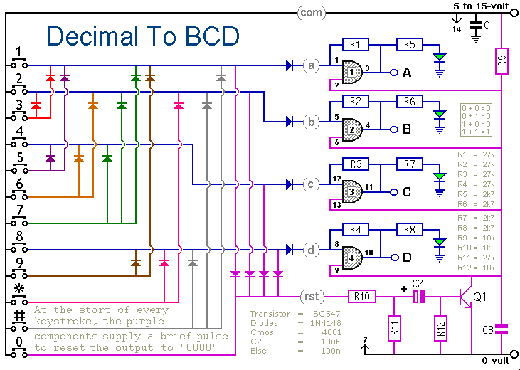
When a keypad switch is pressed, this circuit reproduces its value in Binary Coded Decimal (BCD) format. A 12-keypad is used, but it can be expanded to 16 keys for Hexadecimal to BCD conversion. The circuit consists of two...
The series of light switches is slightly different from traditional designs. These light switches can operate directly on the AC power network. The main components of the circuit include a TRIAC and a Light Dependent Resistor (LDR). The circuit...
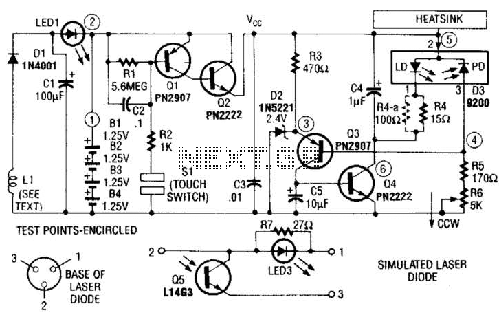
A laser diode TOLD9200 (Toshiba) serves as a source of laser light. Q3, Q2, and SI constitute a touch switch to control the laser. L1 is an RF pickup coil designed to extract energy from an RF-type battery charger....
Here is an updated schematic featuring the RF Solutions receiver along with several minor additions. The design includes additional circuitry to manage the signals effectively. The updated schematic incorporates an RF Solutions receiver, which is essential for receiving radio frequency...
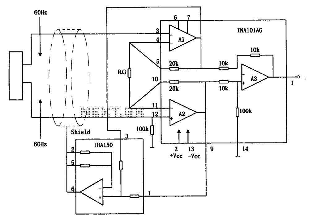
The circuit diagram illustrates a hum elimination instrument amplifier circuit. The amplifier stages A1 and A2 utilize the integrated operational amplifier INA101, followed by stage A3 which employs the INA105. A feedback circuit is incorporated to reduce the power...
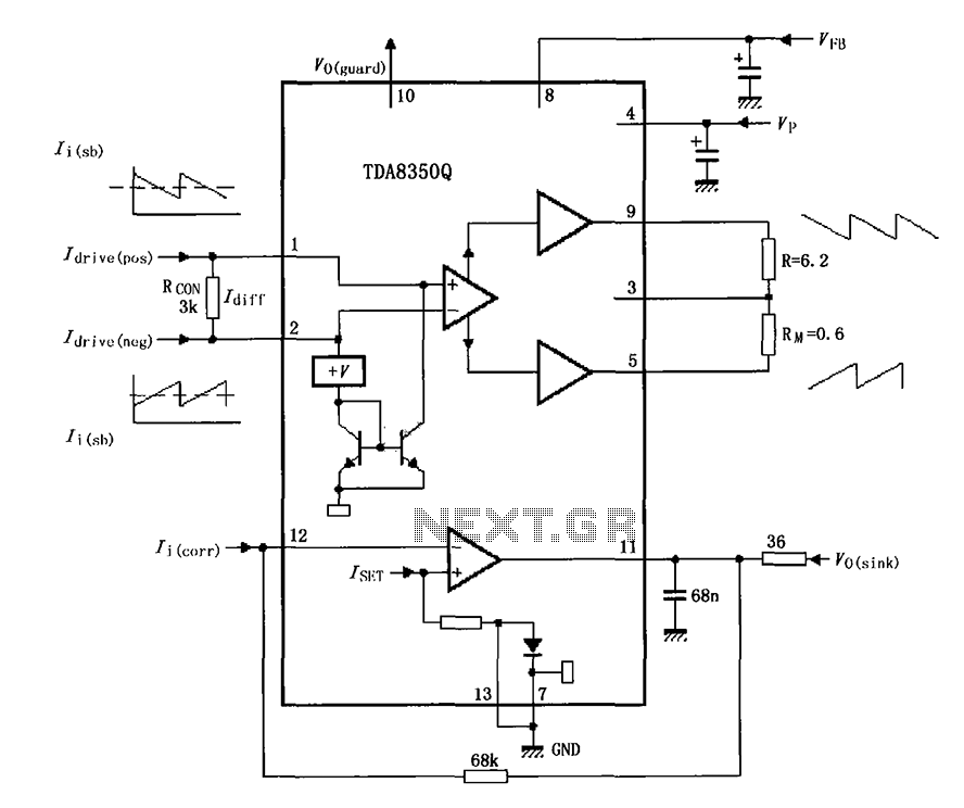
The TDA8350Q test circuit includes a push-pull amplifier configuration where the output terminal resistor serves as a dummy load for testing an alternative deflection coil. The TDA8350Q is a high-performance integrated circuit designed for use in television and display systems....