
Low Cost High Level Preamp and Tone Control Circuit

The use of Junction Field Effect Transistors (JFETs) in the preamplifier and tone control circuit offers several advantages, particularly in audio applications where low noise and high input impedance are critical. JFETs are known for their high input impedance, which allows them to interface effectively with high-impedance sources without loading them down. This characteristic is essential in maintaining signal integrity, especially in sensitive audio applications where the preservation of the original signal is paramount.
The preamplifier section typically consists of a single JFET configured in a common source arrangement. This configuration provides voltage gain while ensuring that the input impedance remains high. The output of the preamplifier can be fed into a tone control circuit, which may utilize additional JFETs or operational amplifiers to shape the frequency response according to user preferences. The tone control circuit generally includes filters that can boost or cut specific frequency ranges, allowing for customization of the audio output.
To further enhance performance, careful attention must be given to the layout of the circuit. Proper grounding techniques and the use of shielded cables can help minimize noise and interference, which is particularly important in low-level audio signals. Additionally, the choice of passive components, such as capacitors and resistors, can significantly affect the overall performance and should be selected for their low noise characteristics.
Overall, the integration of JFETs in the preamp and tone control circuit not only contributes to low noise operation but also supports high fidelity audio reproduction, making it an ideal choice for high-quality audio systems.For the best advantage as a low noise high input impedance device, the preamp and tone control uses JFET. If the circuit reaches harmonic distortion levels of. 🔗 External reference
Related Circuits
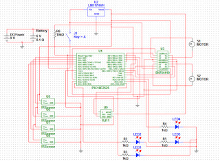
The objective of the project is to develop a robot capable of following a black line on a white sheet of paper and navigating through a maze constructed from these materials. The maze specifications include black lines with a...
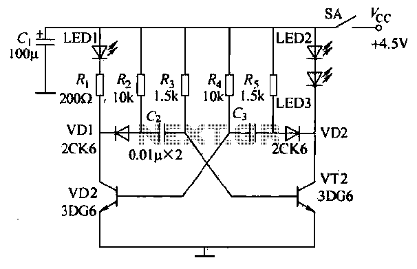
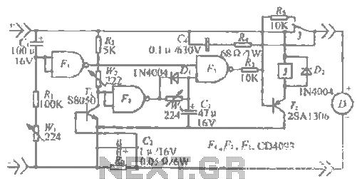
The infrared transmitter circuit, as depicted in Figure 18-la, utilizes transistors VT1 and VT2 along with RC components to create an astable multivibrator. The circuit operates with VT1 and VT2 receiving base bias from resistors, and closing switch SA...
This active antenna schematic can be used to frequency range from 10 KHz to 100 MHz. The length of the Antenna can be between 0.5 to 1 meter long. The power consumption is 20-30mA. More: Use the shortest possible...
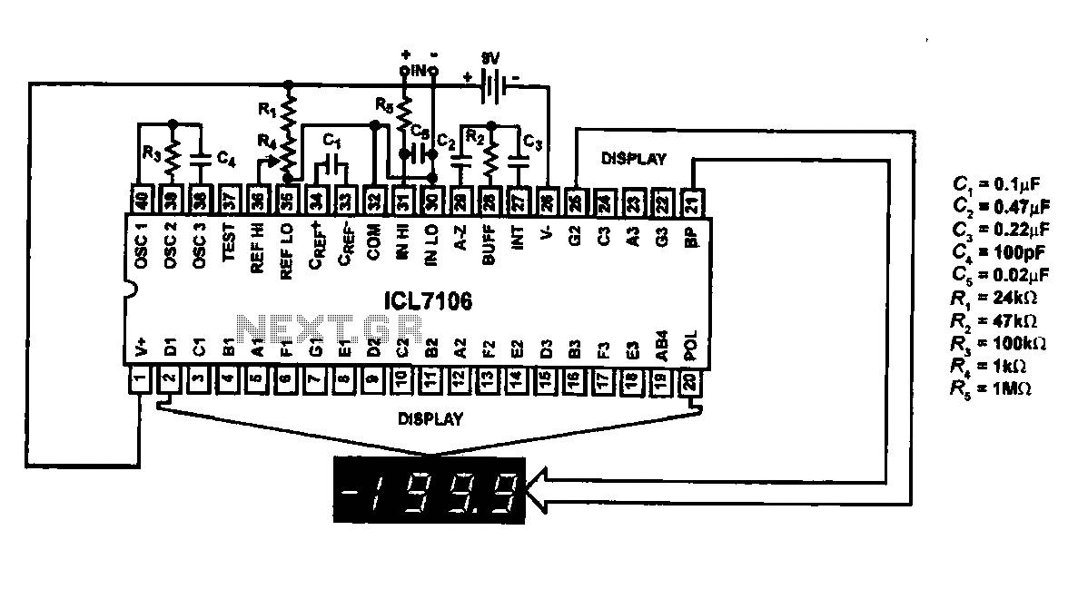
This circuit utilizes the ICL7106 / ICL7107 chip to drive a liquid crystal display (LCD). In this configuration, the ICL7106 / ICL7107 functions as a signal measurement and analog-to-digital (A/D) converter. It detects an analog input signal, amplifies it,...
The "R-h sampling circuit limit order" aims to reduce the sampling resistor. A DC voltage level can be positioned between the components. The circuit includes a line amplifier that allows for magnification adjustments and is designed to protect against...
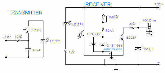
The transmitting section of this infrared tx-rx is unusually simple but it works rather well: the infrared LED pulses at a frequency of 160Hz and its range, with its receiver, is between 2 and 4m depending on the transformer...