
Using ICL7106-ICL7107 chip liquid crystal display circuit

The ICL7106 and ICL7107 are integrated circuits designed for high-precision analog-to-digital conversion. They are commonly used in applications that require accurate measurement of voltage levels, such as digital voltmeters and other instrumentation. The operation begins with the analog input signal being fed into the A/D converter. The chip samples the input and converts it into a digital format through a process called successive approximation.
The output of the conversion is then sent to the liquid crystal display. The ICL7106/7107 is capable of driving a 3.5-digit display, which allows it to show values from 0 to 1999. The display typically requires a few additional components to function correctly, including resistors for setting the reference voltage and capacitors for stabilization.
In this circuit, a stable voltage reference is crucial for accurate measurements. A common approach is to use a voltage reference IC, which provides a precise voltage level that the A/D converter can use as a baseline for converting the analog signal. Additionally, filtering capacitors are often included in the design to minimize noise and ensure a clean signal is presented to the converter.
The circuit may also incorporate a microcontroller or additional logic to manage the display and handle user inputs, such as selecting measurement ranges or initiating calibration procedures. Overall, the ICL7106/7107-based circuit offers a reliable solution for converting analog signals into a readable digital format, making it suitable for various electronic measurement applications.It shows using ICL7106 / ICL7107 chip liquid crystal display circuit. In this circuit, ICL7106 / 7107 is a signal measurement and A / D converter circuit, an analog input signal by detecting it, amplified to the digital display circuit, the result of the measurement with digital display.
Related Circuits
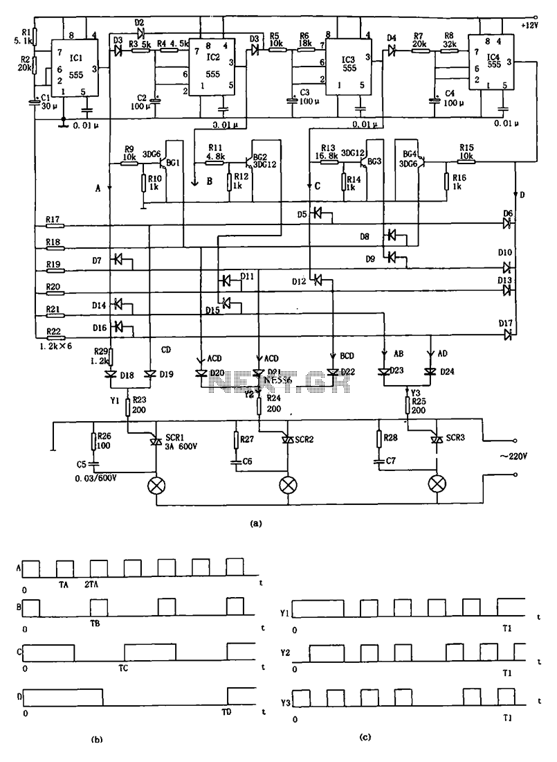
The decorative lamp control circuit is illustrated in the figure. The controller comprises a pulse generator, a frequency divider, a matrix circuit, and a thyristor control circuit. Components IC1, R1, R2, C1, and others form a multivibrator where the...
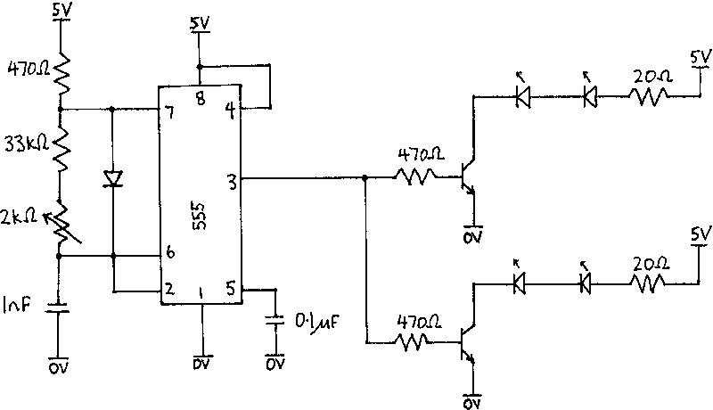
The infrared receiver requires the infrared light to be modulated at 38 kHz, which corresponds to a period of 26 µs. The specifications for the receiver suggested using a 50% duty cycle; however, this configuration did not perform as...
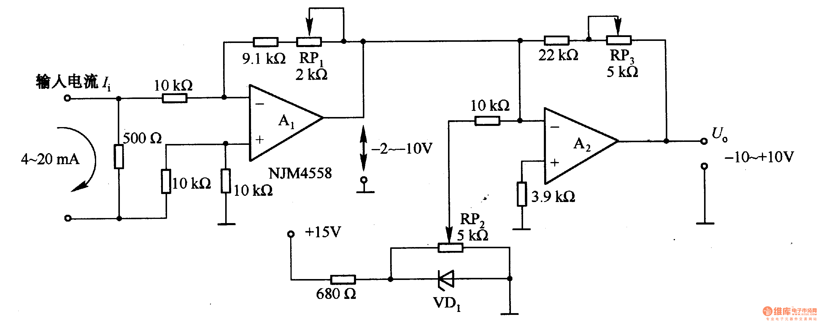
Figure 1-42 (a) is a voltage/current conversion circuit that converts a 0-10V input voltage into a 4-20mA output current. Adjusting resistor RP2 can set the input voltage (Ui) to 0V, resulting in an output current (I) of 20mA; similarly,...
The two circuits di atas illustrate opening a relay contact a short time after the ignition or light switch is turned off. The capacitor is charged and the relay is closed when the voltage at the diode anode rises...

The LED running light project can be easily implemented using microcontrollers, particularly the Microchip PIC microcontroller. This project utilizes the PIC16F877A microcontroller, which features a 40-pin IC configuration, with LEDs connected to port B. The LEDs twinkle in accordance...
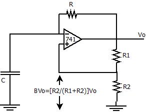
The positive feedback comparator circuit enhances the gain of the operational amplifier (op-amp), facilitating rapid switching between the two states of a multivibrator. This positive feedback also introduces hysteresis into the circuit. A capacitor, denoted as `C`, is connected...