
low cost high speed photography

The schematic design incorporates a linear voltage regulator to supply a stable voltage to the controller, enhancing the reliability of the system. The variable voltage generator on PB1 allows for fine-tuning of the reference voltage, which is critical for the accurate operation of the sensor circuit. The voltage divider, configured to output 2.5 volts, ensures that the signal input aligns with the expected operational parameters of the transducer, allowing it to detect changes in the environment effectively.
In terms of the sensor's performance, the sensitivity is a double-edged sword; while it enables the detection of subtle changes, it also increases the likelihood of false triggers. The integration of an operational amplifier could significantly improve the signal-to-noise ratio, thereby reducing erroneous activations caused by ambient light changes, such as the switching of room lights.
The implementation of a dead time parameter set to four seconds serves as a practical approach to mitigate the effects of false triggering by ensuring that the sensor does not respond to rapid successive stimuli. This feature is particularly beneficial in applications such as photography, where precise timing is essential to capture the desired moment without interference.
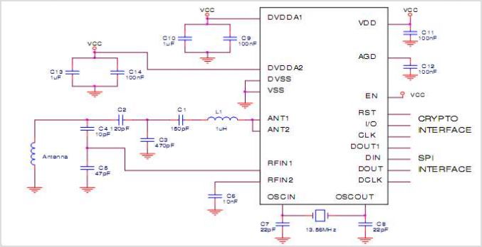
Overall, this circuit design not only facilitates the exploration of dynamic phenomena like water droplets but also encourages users to engage in further experimentation and learning within the realm of sensor technology and photography. The combination of a well-calibrated reference voltage, a robust sensor circuit, and thoughtful timing parameters creates a versatile platform for capturing unique visual representations of physical processes.And here is the final part of the entry, starting with the schematic that I finally used. The core is the same as before. But now there is a linear voltage regulator for the controller. Also shown here is the serial interface and most importantly, the sensor circuit. The sensor circuit consists of two parts. First, the reference voltage on PB1 is generated with a variable voltage generator. The voltage can be varied between 2 and 3 volts. The second part is the signal input, also a voltage divider at 2. 5 volts and the transducer. I adjusted the reference voltage so that the LED just stops flashing without any input activity. Everything works. The main improvement would probably be on the sensor. It has to be very sensitive, and this leads to false triggers. E. g. switching the room light on or off trigger it. Perhaps an amplifier would help. As a work-around I set the dead time parameter to four seconds, so it would only trigger once per photo. I was able to take a few really interesting pictures. It is quite amazing how water behaves and the stroboscope makes it possible to explore that. I put a few pictures on flickr and there will be more. It is quite useful to look at some howtos on water drop photography. And of course you can experiment quite a lot. 🔗 External reference
Related Circuits

This is a simple low pass filter that can be used at any audio circuitry. It uses the 741 opamp. More: Do not forget to use double power supply of 5 volts. You can use 2 batteries as shown...
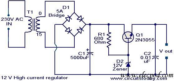
Since my page was first posted, I have received a number of emails asking about a high current power supply. I looked around, but couldn't find one that was suitable. So, I designed this. It is a linear supply,...
The EUA2032 is a high-efficiency, 2.5W mono class-D audio power amplifier. A newly developed filterless PWM modulation architecture further reduces EMI and THD+N, as well as eliminates the LC output filter, thereby reducing the external component count, system cost,...
This project page has evolved into a design discussion. Constructive suggestions and collaboration are still welcome. Please refer to the comments section. The project focuses on the development of an electronic circuit design, which has transitioned from a simple project...
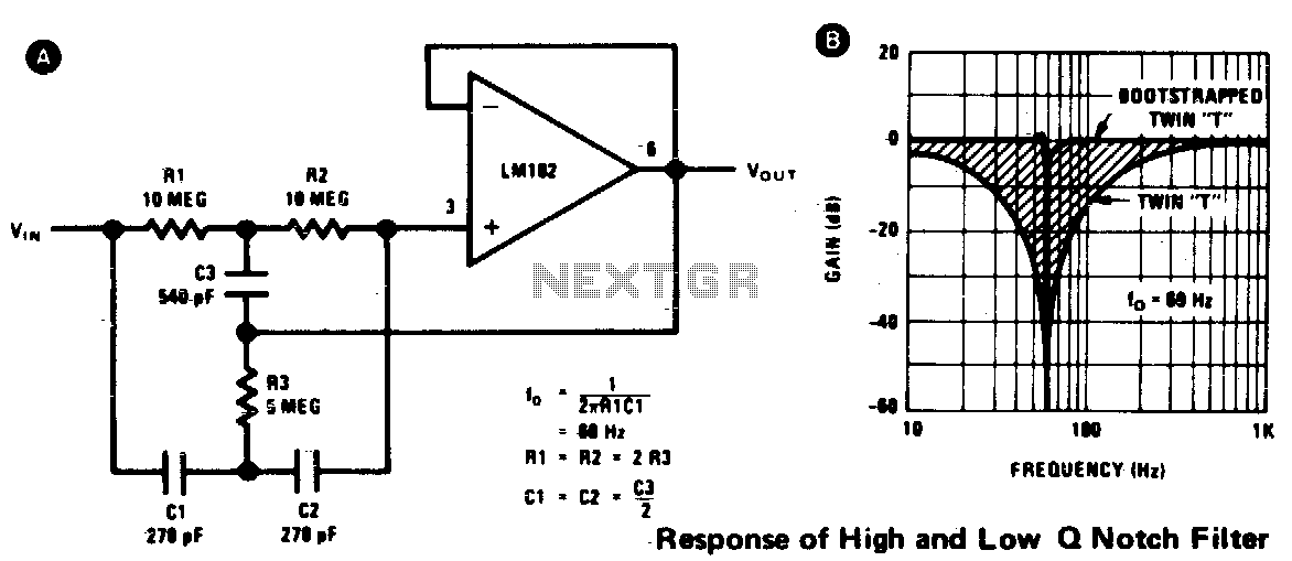
A twin-T network is connected to an LM102 to create a high-Q, 60 Hz notch filter. The junction of R3 and C3, typically grounded, is bootstrapped to the follower's output. The low impedance of the follower ensures that neither...
This voltage regulator circuit can deliver up to 3A at a 12V output voltage. The circuit is suitable for applications where a current exceeding 3A is required. Integrated circuit (IC) regulators with such high current ratings are difficult to...