
Low-Dropout (LDO) Voltage Regulator
 Voltage Regulator")
The low-dropout (LDO) regulator is a crucial component in power management systems, providing a stable output voltage despite variations in input voltage and load current. This specific LDO design utilizes a single PNP transistor, which simplifies the circuit while maintaining efficiency.
In this configuration, the PNP transistor operates in the active region, allowing for a minimal voltage difference between the input and output, which is essential for low-dropout applications. The output voltage is regulated by adjusting the base current of the PNP transistor, which is influenced by the feedback from the output voltage. A resistor divider can be used to set the desired output voltage level, ensuring that the output remains stable under varying load conditions.
The circuit's performance is closely tied to the load current; as the load increases, the regulator must adjust the base current to maintain the output voltage. This characteristic makes the LDO suitable for powering sensitive electronic devices that require a stable voltage supply.
In addition to the PNP transistor, the circuit may include bypass capacitors at the input and output to filter noise and stabilize the voltage levels. The choice of these capacitors can significantly impact the transient response and overall performance of the LDO regulator, particularly during sudden changes in load.
Overall, this single PNP transistor LDO regulator design offers a compact solution for voltage regulation in various electronic applications, balancing simplicity with effective performance.This is a Low-dropout (LDO) Regulator circuit, constructed by using only a single PNP transistor. This circuit is directly related to load current. At very low.. 🔗 External reference
Related Circuits
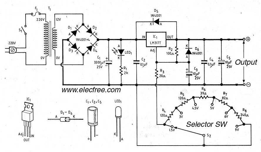
Typically, the study of electronic power supplies starts with batteries, such as 9 volts, 1.5 volts, and 6 volts. However, there are disadvantages associated with this approach. The exploration of electronic power supplies often begins with the use of batteries,...
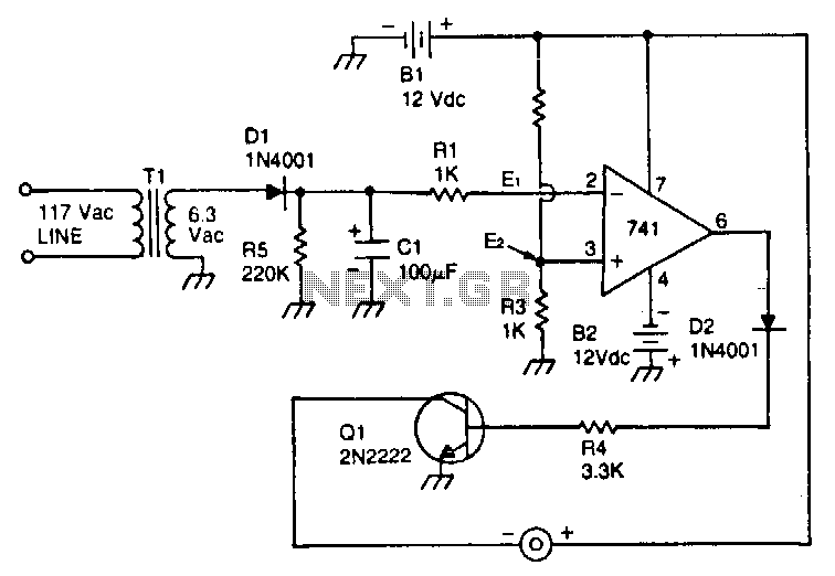
This circuit utilizes a type 741 operational amplifier (op amp) configured as a voltage comparator. One input of the 741 is connected to a reference voltage, sourced from a 12-V battery, via a resistor voltage divider. The voltage at...
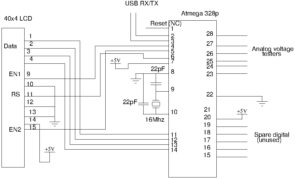
Drive a four-line LCD panel using an Arduino. The project initially aimed to control the LCD for displaying arbitrary information but evolved to include functionalities such as timekeeping, EEPROM read/write operations from the Atmel 328p, and voltage measurement. Multiple...
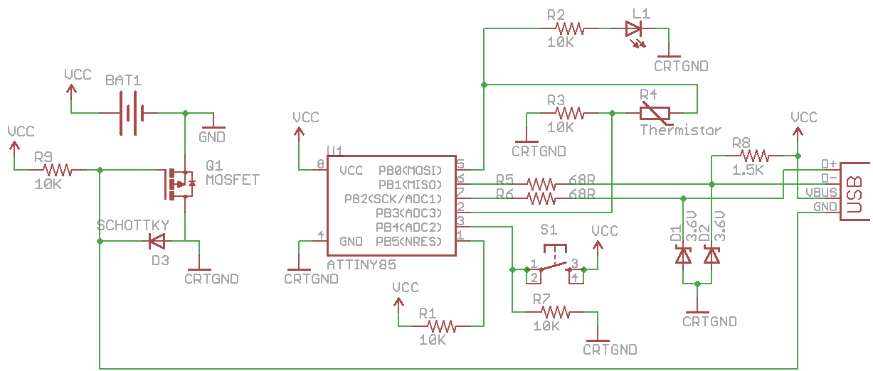
CRTGND is not equivalent to GND; CRTGND connects to the MOSFET drain or Schottky diode. A disadvantage of this circuit is the voltage drop when powered from the USB side due to the diode. The USB voltage can fluctuate...
This is a schematic diagram of a micropower voltage-controlled oscillator circuit. This circuit can generate square and triangle wave outputs and only requires minimal power. The micropower voltage-controlled oscillator (VCO) circuit is designed to produce both square and triangle waveforms,...
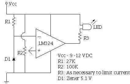
An ECU must have a way to monitor battery voltage. Here is a simple op-amp based circuit which will illuminate the LED when the battery voltage drops to a certain level. The turn-on point is set with R2. You...