
Micropower VCO (Voltage-Controlled Oscillator)
")
The micropower voltage-controlled oscillator (VCO) circuit is designed to produce both square and triangle waveforms, making it suitable for various applications in signal generation and modulation. The circuit typically consists of a few key components including operational amplifiers, resistors, capacitors, and a voltage control input.
In this design, the operational amplifier is configured in an astable multivibrator configuration, which allows for the generation of square waves. The frequency of oscillation can be adjusted by varying the resistance and capacitance values in the feedback loop. The triangle wave output is derived from the integration of the square wave signal. This is achieved by connecting a capacitor in the feedback path, which smooths the transitions of the square wave, resulting in a linear ramp-up and ramp-down voltage characteristic.
The power consumption of this circuit is kept to a minimum, making it ideal for battery-operated devices or applications where energy efficiency is crucial. The VCO can be controlled by an external voltage input, allowing for dynamic frequency adjustments based on varying control voltages. This feature enhances the versatility of the circuit in applications such as frequency modulation, waveform generation, and timing applications.
The design may also include additional components such as diodes for clamping the output levels and ensuring stability, as well as filtering capacitors to reduce noise and improve signal integrity. Overall, this micropower voltage-controlled oscillator circuit is a compact and efficient solution for generating precise waveform outputs in a variety of electronic systems.This is a schematic diagram of a micropower voltage-controlled oscillator circuit. This circuit can generate square and triangle wave outputs and only need.. 🔗 External reference
Related Circuits
A power source providing 2.5V DC at 10µA is utilized to drive a pager motor. The motor activates between 2.3V and 2.5V, and deactivates between 1.2V and 1.5V. The circuit design has been breadboarded by multiple individuals, showing consistent...
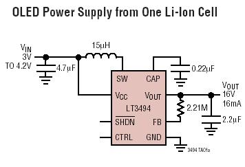
The LT3494 and LT3494A are low-noise boost converters that integrate a power switch, Schottky diode, and output disconnect circuitry. These devices utilize an innovative control technique that results in minimal output voltage ripple and high efficiency across a broad...
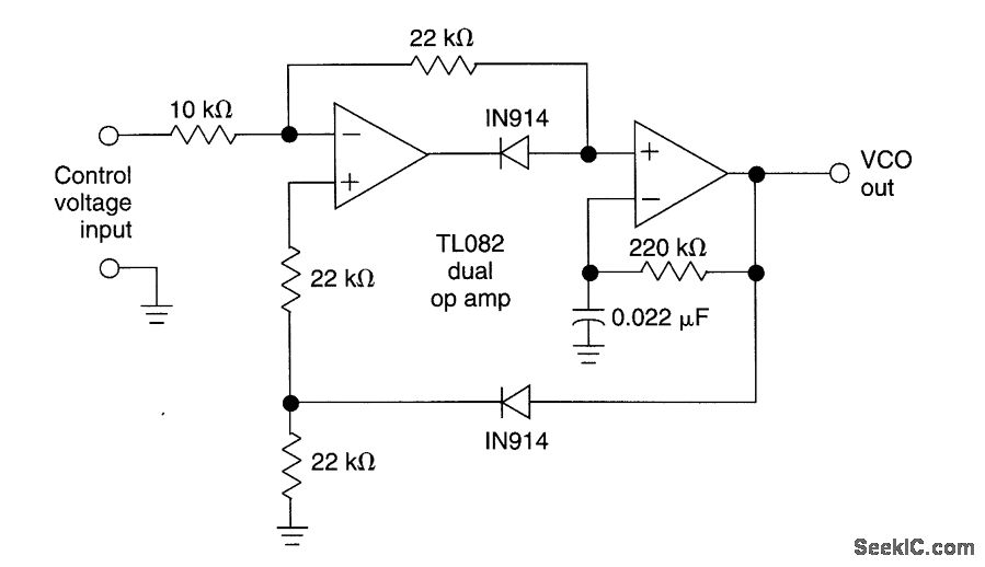
This circuit utilizes a dual operational amplifier (TL082) to create a voltage-controlled oscillator (VCO). The specified component values allow the output frequency to range from 100 Hz to 10 kHz when the input control voltage varies between 0.05 V...
This document presents a family of intermediate frequency (IF) voltage-controlled oscillators (VCOs) that operate within a frequency range of 45 MHz to 650 MHz. The integrated circuits (ICs) are packaged in 6-pin SOT23 configurations. The MAX2608 model exhibits a...

The main oscillator is printed in blue and is voltage controlled. In this construction, the VCO range is 88 to 108 MHz. As you can see from the blue arrows, some energy goes to an amplifier and some energy...

This paper is a tutorial discussion of intermediate frequency voltage-controlled oscillator (IF VCO) design considerations. A Colpitts topology is analyzed and used to explore performance impacts. The discussion on IF VCO design considerations focuses on the critical aspects of voltage-controlled...