
low fuel light circuit

The fuel gauge sender is a critical component in monitoring the fuel level within a tank. In this scenario, the sender operates on a variable resistance principle, where the resistance value changes based on the fuel level. When the tank is devoid of fuel, the sender outputs a resistance of 100 ohms. This value serves as a reference point for the fuel gauge system.
To ensure accurate fuel level readings, a trigger point is established at 80 ohms. This threshold indicates a level of fuel that is low but not completely empty, allowing for timely alerts to the driver regarding the need for refueling. The choice of 80 ohms as a trigger reading is strategic; it provides a buffer that prevents the risk of running out of fuel entirely while still allowing for a practical range of operation.
In a typical schematic, this sender would be connected to a fuel gauge via a wire, often referred to as a sender wire. The gauge itself would interpret the resistance from the sender and convert it into a visual representation of the fuel level, usually through a needle on a dial or a digital readout. The circuit may also include a microcontroller that processes the resistance values and triggers an alarm or warning light when the resistance drops to the 80-ohm threshold, indicating the need for refueling.
Additional components may include resistors for calibration, capacitors for noise filtering, and possibly a voltage regulator to ensure stable operation of the gauge and sender circuit. Proper grounding and shielding techniques should be applied to minimize interference from other electrical systems within the vehicle, ensuring that the fuel level readings remain accurate and reliable under various operating conditions.I`ve done some research and found that sender will read 100 ohms when the fuel tank is empty, so a trigger reading of 80 ohms would be ideal.. 🔗 External reference
Related Circuits
This circuit regulates a DC power output and has a wide range of applications. It can be utilized to control the speed of a motor, a pump, a toy train, or the brightness of an LED or lamp. Essentially,...
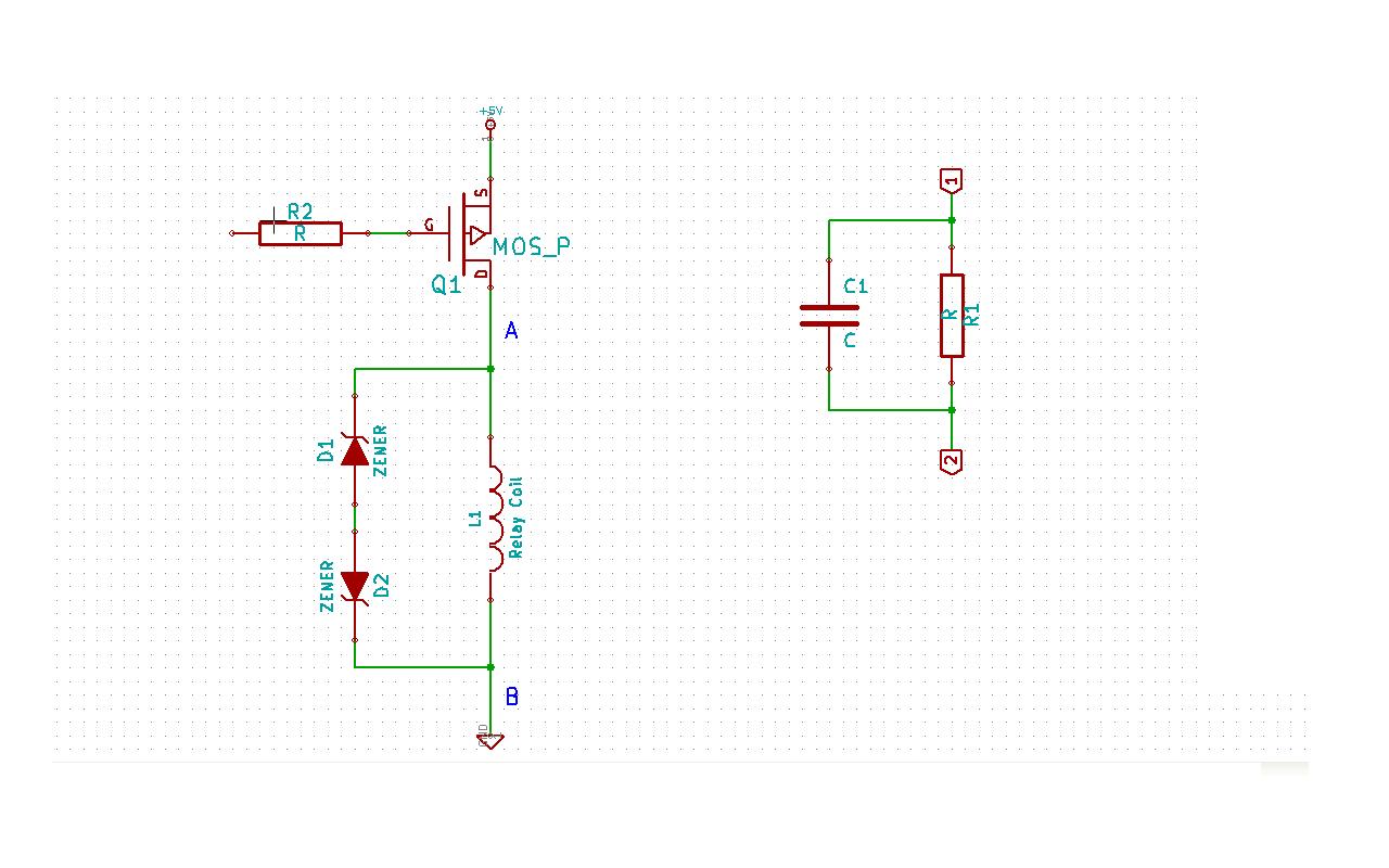
Although this may be a basic question, there is still some struggle with it. In this schematic, two zener diodes D1 and D2 are connected back-to-back across relay coil L1. The breakdown voltage (BVds) is -30V for Q1. The...
The circuit diagram for a multiple output digital camera power supply using the MAX1802 is illustrated below. The MAX1802 chip features two buck converters and three boost converters. It accepts an input voltage range of 2.5 to 11V and...
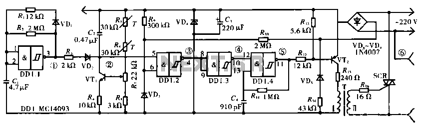
The circuit operates using a temperature stabilizer derived from the main oscillator (DD1.1), along with components including C1, R1, R2, and VD1. It incorporates a monostable multivibrator formed by R3, VD2, VT1, C2, R4, DD1.2, R7, and R8, as...
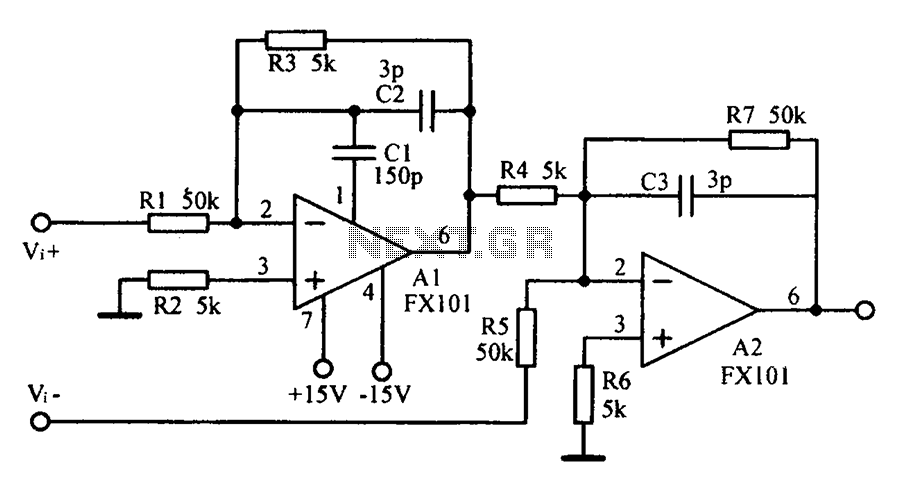
Common mode input voltage up to a difference of 100V enlarged circuit diagram. The circuit diagram described features a design capable of handling a common mode input voltage with a differential range of up to 100V. Such a configuration is...
A light/dark sensing circuit is highly useful and versatile for various renewable energy projects, including automatic lighting and security systems. The article on Light Dependent Resistors (LDR) explains how an LDR can be employed in simple circuits to control...