
LM741 Light Dark Sensor
The light/dark sensing circuit leverages the properties of an LDR to detect ambient light levels. When light levels fall below a predetermined threshold, the circuit activates a control element, such as a relay or a MOSFET, to switch on a connected load, such as an LED spotlight. The circuit typically consists of an LDR, a potentiometer for adjustable sensitivity, a transistor or MOSFET to amplify the control signal, and a relay for switching higher loads if necessary.
The LDR acts as a variable resistor, changing its resistance based on the light intensity. In low light conditions, the resistance increases, causing a voltage drop across the LDR that can be detected by the transistor's base. The addition of a smoothing capacitor helps stabilize the voltage and prevent rapid toggling of the relay, ensuring a more reliable operation.
For low-power applications, the relay can be eliminated, and a MOSFET can be integrated instead. The STP36NF06 MOSFET is a suitable choice due to its ability to handle higher currents with lower power losses compared to traditional relays. The circuit can be designed to either activate in darkness or light, depending on the configuration of the LDR and resistors.
This circuit is particularly advantageous for renewable energy systems, where efficient energy use is critical. It can be applied in various contexts, from outdoor lighting to security systems, providing an automated response to changing ambient light conditions. Customization options allow users to tailor the circuit to their specific needs, ensuring versatility and practicality in deployment.A light/dark sensing circuit is extremely useful and versatile in a wide range of renewable energy projects from automatic lighting to security systems. In our article Light Dependent Resistor we explained how an LDR can be used in simple circuits to control devices according to the ambient levels of lighting - for example, automatically turning o
n a lamp above a doorway at nighttime. The circuits provided in that article were very basic and therefore not without their problems. The main problem is that the automatic turn-on is not sharp - i. e. rather than switching the lamp on fully as soon as ambient levels of light fall to a fixed point, the lamp turns on slowly getting brighter and brighter as light levels fall. This is not a serious problem when controlling a lamp - in fact it may even be desirable - however when controlling other devices (such as a night vision camera) it is not optimal.
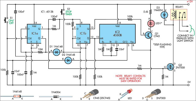
One way around this is to use a relay, however a typical 12 Volt relay draws 300-500mW of power - a significant waste of energy when a 1 Watt LED spotlight for example is to be controlled. 1st Nov 2007 Update - We have modified the schematic diagram above with the addition of a 220uF smoothing capacitor between the base of transistor Q1 and ground.
Without this capacitor, the relay chatter (relay switching on and off many times per second) was terrible around the switch on/off light level. By adding the capacitor, relay chatter was completely eliminated. According to the designer of this circuit, the relay will be closed only when "NO light falls on LDR1", however, in testing this circuit proved to work very well with the user able to adjust the potentiometer (P1) to automatically close the relay at whatever light level they chose.
By swapping the postitions of the 10K resistor (R1) and the LDR (LDR1), the relay will be closed when the LDR is under light rather than under darkness. Therefore a device can automatically be switched off at nighttime. Since this circuit still contains a relay we need to make some changes* to reduce the amount of power to make it more suitable for renewable energy powered low-current applications.
* Where devices of more than a couple of Amps are to be powered, the energy loss in the relay becomes insignificant and so the above illustated circuit should be used as is. If this circuit is to be used to provide <200mA of current (for example, to power just ONE 12V MR16 LED spotlight with around 100mA), the relay can be removed altogether as illustrated below: If more current is required - for example to power a string of LED spotlights - the transistor can be replaced by a MOSFET. A MOSFET is similar to a transistor, but it can carry much more current. In our testing we used an STP36NF06 MOSFET since that`s what we had lying around. Since the vast majority of people do not have the necessary expertise and equipment to put together one of these circuits, we are happy to put one together for you according to your exact needs.
The MOSFET version of the circuit (suitable for maximum total output currents of 2 to 3 Amps) is now available from the REUK Shop and is pictured above. Click here for more information and to make a purchase: Light/Dark Sensor Circuit (Low Current). NEW - We now also have the relay version of the circuit (suitable for maximum total output currents of 10 to 12 Amps) and it is also available in the REUK Shop: Light/Dark Sensor Circuit (Relay).
If you require a bespoke light/dark sensor circuit - for example, one which activates in light rather than in darkness contact neil@reuk. co. uk directly with details of your requirements. Prices start from around £10 per circuit including all components. 🔗 External reference
Related Circuits
A humidity sensor can be utilized to provide an alert for boat leakage or to notify when books are at risk of being damaged due to heavy rain affecting a compromised roof. Humidity sensors are essential devices that measure the...
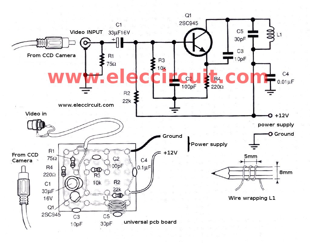
The CCD camera sensor is a very useful device that is compact in size while providing excellent quality. It can be easily installed with a television through the video input terminals, allowing for the transmission of modulated video signals...
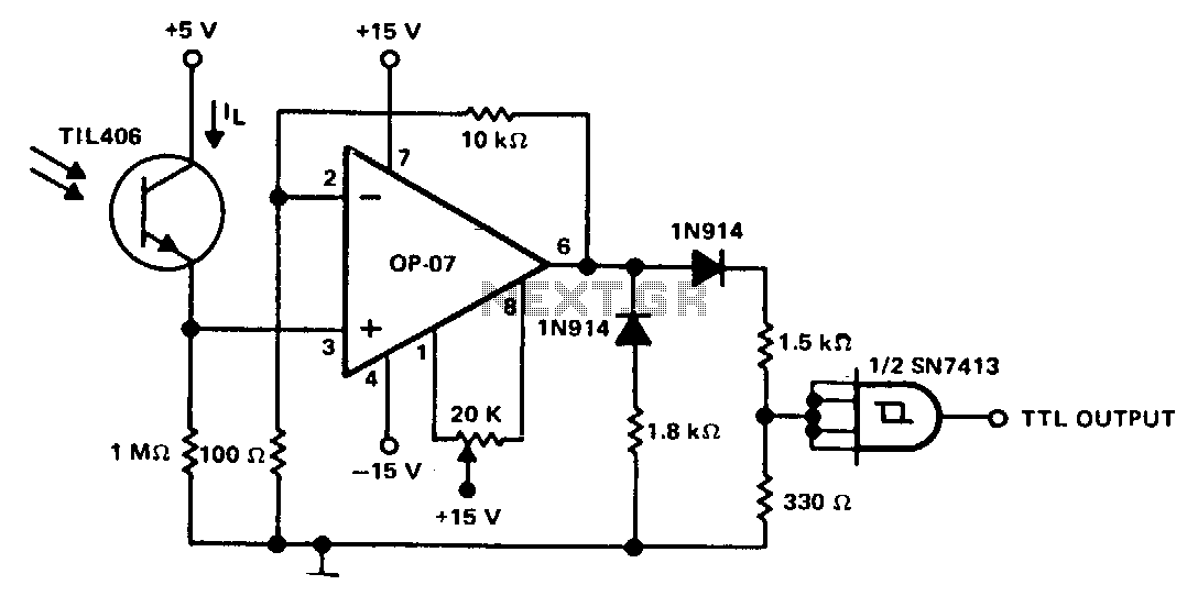
This circuit is designed to detect low light levels at the sensor, amplify the signal, and provide a TTL-level output. When the optical sensor detects low-level light, its output is small and must be amplified. An amplifier with very...
On a mountain bike, a common issue with traditional flashing LED lights from stores is the frequent problem of flat batteries and lights detaching. As an electronics student, a better solution was sought. A front wheel with a built-in...
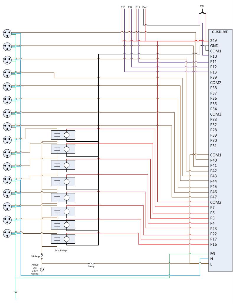
This is the circuit diagram for the Comfile CUSB-36R Programmed Christmas Lights. If it is difficult to read, please contact me via email at [email protected], and I will provide a more detailed schematic. The Comfile CUSB-36R can either drive...
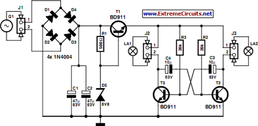
This 9-minute timer switch is designed to control lighting in a toilet or bathroom. The timer is activated by pressing switch S1 and deactivated by pressing S1 again. If the switch is not turned off, the light will automatically...
Warning: include(partials/cookie-banner.php): Failed to open stream: Permission denied in /var/www/html/nextgr/view-circuit.php on line 713
Warning: include(): Failed opening 'partials/cookie-banner.php' for inclusion (include_path='.:/usr/share/php') in /var/www/html/nextgr/view-circuit.php on line 713