
low power 12000 volt power

This circuit operates by leveraging a transformer principle, where the 120 VAC input is stepped up to a high voltage using the 6 kV camera flash trigger coil. The primary winding of the transformer is connected to the AC power source, while the secondary winding generates the high voltage output. The isolation of the output from the power line is critical for safety, ensuring that there is no direct electrical connection between the high voltage output and the mains supply.
The circuit typically includes a rectifier to convert the high voltage AC output from the transformer into a DC voltage. A high-voltage diode is employed in this stage, capable of withstanding the elevated voltages generated. Following the rectification process, a filter capacitor may be used to smooth the output voltage, providing a more stable DC supply for the ion generator.
Given the high voltage levels involved, it is essential to incorporate safety measures in the design. This includes using appropriately rated components, such as high-voltage capacitors and diodes, and ensuring that all connections are secure and insulated to prevent accidental contact. Additionally, the circuit should be housed in a non-conductive enclosure to further minimize the risk of electric shock.
Due to the ability of the circuit to produce high voltage at low current, it is important to handle it with care. The generated voltage, while limited in current, can still pose a significant risk of electric shock. Proper precautions, such as using insulated tools and wearing protective gear, should be taken when working with or testing the circuit to ensure safety.If you need about 12, 000 volts DC for an ion generator this circuit might be the ticket. It draws power from the 120vac power line but it uses a small 6KV camera flash trigger coil. The output signal is isolated from the power line. Although the circuit can only deliver about 5uA of current it can produce dangerous shocks, so be careful. 🔗 External reference
Related Circuits
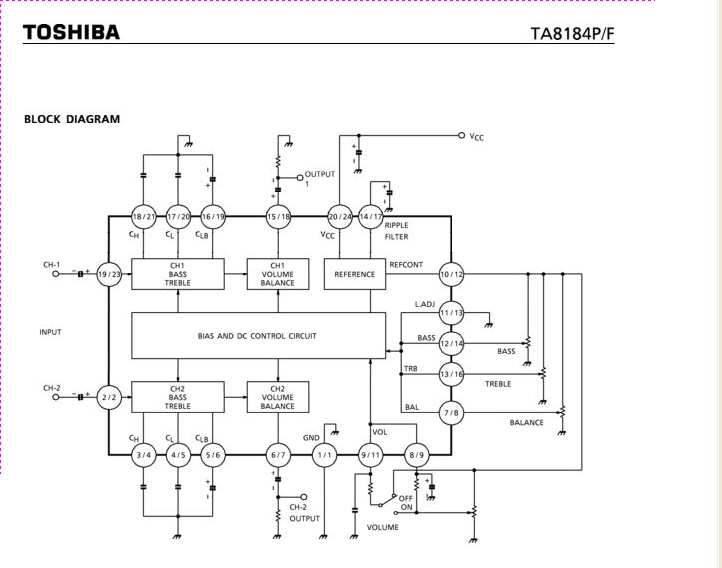
The TA8184P and TA8184F are DC-controlled integrated circuits designed for dual volume, balance, and tone (bass and treble) control. These ICs are suitable for applications in car stereos, radio cassette players, music centers, and TV multiplex sound receivers, providing...
This circuit is a simple form of the commercial UPS, the circuit provides a constant regulated 5 Volt output and an unregulated 12 Volt supply. In the event of electrical supply line failure the battery takes over, with no...
Self-switching power supply. One of the main features of the regulated power supply circuit being presented is that, although a fixed-voltage regulator LM7805 is used in the circuit, its. The self-switching power supply circuit utilizes the LM7805 voltage regulator to...
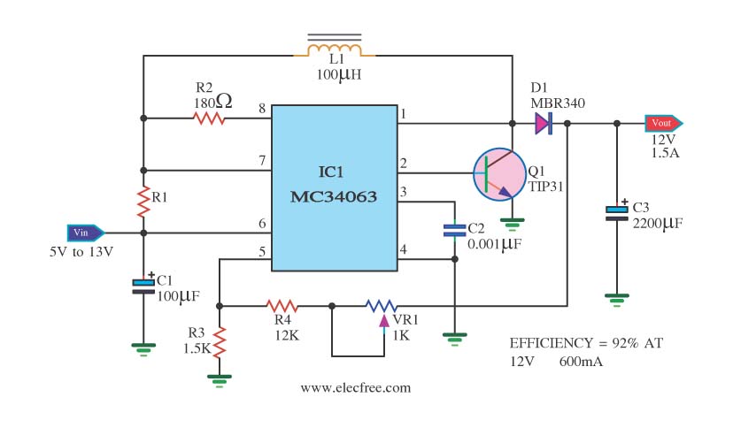
The circuit is a battery-powered voltage regulator that outputs 12V at 1.5A. It accepts an input voltage range from 5V to 13V. The circuit utilizes the MC34063 integrated circuit, making it a straightforward design. The circuit primarily functions as a...
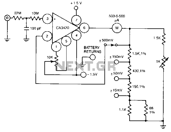
A resistance of 1,000,000 MΩ takes advantage of the high input impedance of the CA3420 BiMOS op-amp. Only two 1.5-V AA-type penlite batteries are required for use. Full-scale deflection is ±500 nV, ±150 mV, and ±15 mV. The circuit utilizes...
The circuit is designed to deliver a surge current of 12 amps, offering performance that meets or surpasses that of typical commercial units. Additionally, it incorporates a current limiting feature, providing a level of reliability that is superior to...