
Voltage Regulator 12V 1.5A for Battery by MC34063

The circuit primarily functions as a step-up (boost) converter, which is capable of converting a lower input voltage to a higher output voltage. The MC34063 is a versatile DC-DC converter IC that can be configured for step-up, step-down, or inverter applications. In this case, it is configured to boost the input voltage to the desired 12V output.
Key components of the circuit include the MC34063 IC, an inductor, a diode, and output capacitors. The inductor stores energy when the switch within the IC is closed and releases it to the output when the switch opens. The diode is used to prevent backflow of current, ensuring that the energy is directed towards the load. Output capacitors smooth the voltage to provide a stable 12V output.
The input voltage range of 5V to 13V allows for flexibility in battery selection, making it compatible with various battery types, including lithium-ion and lead-acid batteries. The output current capability of 1.5A is suitable for powering a variety of devices that require a stable 12V supply.
To ensure optimal performance, it is important to select an inductor with the appropriate inductance value and current rating, as well as a diode that can handle the output voltage and current without overheating. Additionally, proper layout techniques should be employed in the PCB design to minimize noise and improve efficiency.
This circuit is ideal for applications where a stable 12V supply is required from a lower voltage battery source, such as in portable electronics, battery-powered devices, and renewable energy systems.The circuit is a good battery. It is Control Volttage regulator Output 12V 1.5A , Input Voltage battery 5V-13V Only. Use IC- MC34063 so easy circuit,.. 🔗 External reference
Related Circuits
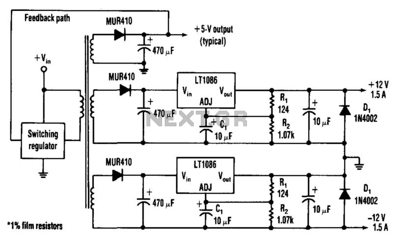
Many applications require highly efficient negative-voltage post regulators with low dropout voltage in switch-mode supplies. A method to achieve effective negative-voltage regulation is by utilizing a low-dropout positive-voltage regulator that operates from a well-isolated secondary winding of the switch-mode...
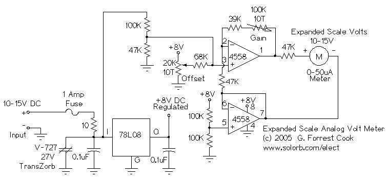
This circuit is used to measure the voltage on a 12V (nominal) lead acid rechargeable battery system. It was specifically designed for use in solar powered systems, but is general enough that it can be used for automotive or...
This is a battery tester circuit. This circuit is used to indicate whether the level of a battery voltage is normal, under-voltage, or over-voltage. The battery tester circuit is designed to assess the voltage level of a battery and provide...
This device is designed to maintain a deep cycle battery using energy harvested from a solar panel. It functions as a combination of a digital clock timer and a solar panel charge controller. Component: .. This circuit serves the dual...
If you want to try a higher voltage with your pedals, try this simple and easy voltage doubler circuit which uses an ICL7660 CMOS Voltage Converter Chip. I have found that JFETs such as the J201 sound much better...
The circuit is designed to fit into a small enclosure that can be placed in a backbox at a location of your choice. It requires only three wires: one for the battery positive voltage, one for the +5 volts...