
low power 5 v switching regulator

The low power 5V switching regulator is designed to efficiently convert a higher input voltage to a stable 5V output while minimizing power loss. Switching regulators are preferred in applications where power efficiency is critical, as they utilize a high-frequency switching element to regulate the output voltage, in contrast to linear regulators that dissipate excess voltage as heat.
The circuit typically consists of an input capacitor to filter the input voltage, a switching element (usually a MOSFET), an inductor to store energy, a diode for rectification, and an output capacitor to smooth the output voltage. The control circuitry often includes a feedback loop that monitors the output voltage and adjusts the duty cycle of the switching element to maintain a constant output voltage despite variations in load current or input voltage.
Key specifications for a low power 5V switching regulator include the input voltage range, output current capability, efficiency rating, and switching frequency. These parameters are critical for ensuring the regulator meets the requirements of the specific application, whether it be in battery-powered devices, portable electronics, or other low-power systems.
The circuit diagram associated with this regulator will typically illustrate the connections between these components, showing how the switching element is driven by a control signal, how the inductor and capacitor form a low-pass filter to produce a stable output voltage, and how feedback is implemented to regulate the output effectively. Proper layout and component selection are essential to minimize electromagnetic interference (EMI) and ensure stable operation under varying load conditions.Low Power 5V Switching Regulator power supply. Go to that page to read the explanation about above power supply related circuit diagram. 🔗 External reference
Related Circuits
The ADF4107 Frequency Synthesizer can be used to implement local oscillators in the upconversion and downconversion sections of wireless receivers and transmitters. It consists of a low noise digital phase frequency detector (PFD), a precision charge pump, a programmable...

An audio power amplifier circuit for a 3-watt stereo amplifier using the MAX 7910 IC is explained below. The audio power amplifier circuit utilizing the MAX 7910 IC is designed to deliver a maximum output power of 3 watts per...
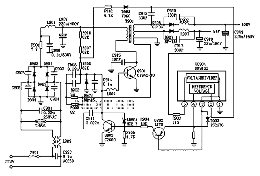
The Hitachi NP8C switching power supply circuit is illustrated in FIG. The Hitachi NP8C power models include CTP236, CEP320D, CRP350D, 450D, Furi HFC-236, 450, and Venus C37-401, C46-1, C563, among others. This circuit was widely used in early Chinese...
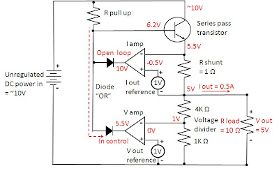
Most power supplies regulate either their output voltage or current at a constant level, depending on the load resistance relative to the power supply's output voltage and current settings. This can be summarized as follows: To accomplish this, most...
This low-noise microphone amplifier is built with the MAT02 produced by PMI. This microphone amplifier is highly efficient and features a very low noise level. The amplification can be set to either 20 dB or 23.5 dB (10x or...

This circuit calculates the difference between two waveforms to determine the voltage across the Current Sense Resistor (CSR). At approximately 33 kHz, the frequency of the positive-going voltage peak (calculated from the time interval at Full Width at Half...