
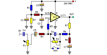
Low noise microphone amplifier circuit

The MAT02 is a precision, low-noise operational amplifier designed for high-performance audio applications. It is characterized by its low input noise voltage and current, making it suitable for amplifying weak audio signals without introducing significant noise. The circuit typically consists of a differential amplifier configuration that enhances the common-mode rejection ratio (CMRR), allowing it to effectively amplify the desired audio signal while minimizing unwanted noise and interference.
The selection of amplification levels (20 dB or 23.5 dB) is achieved through a switch (S1), which connects different feedback resistors in the amplifier circuit. This flexibility allows the user to adjust the gain based on the specific application requirements, whether it be for general audio processing or more sensitive applications like musical instrument amplification or voice recording.
The design considerations for this microphone amplifier include power supply decoupling, which is essential for maintaining low noise levels. Bypass capacitors are typically placed close to the power supply pins of the MAT02 to filter out high-frequency noise, ensuring stable operation. Additionally, proper PCB layout techniques should be employed to minimize ground loops and electromagnetic interference, further enhancing the performance of the amplifier.
Overall, this low-noise microphone amplifier represents a reliable solution for high-fidelity audio applications, combining the advantages of low noise characteristics with adjustable gain settings for versatile usage.This low noise microphone amplifier is build with MAT02 produced by PMI. This mic amplifier is very performant and has a verylow noise level. The amplification can be 20dB or 23. 5dB (10x or 15x ) selected by S1. We aim to transmit more information by carrying articles. Please send us an E-mail to wanghuali@hqew. net within 15 days if we are involve d in the problems of article content, copyright or other problems. We will delete it soon. 🔗 External reference
Related Circuits
This preamplifier is designed to interface with CD players, tuners, tape recorders, and similar devices, providing an AC voltage gain of 4 to drive less sensitive power amplifiers. Given that modern Hi-Fi home equipment often comes with small loudspeaker...
Ensure that connections are verified against the circuit diagram and schematic provided below. This can be utilized while following the tutorial video. The circuit diagram serves as a crucial reference for accurately assembling electronic components in a project. It illustrates...
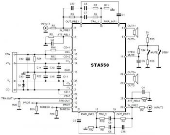
This is a stereo amplifier circuit diagram. The amplifier will produce stereo output channels with a power audio output that can reach up to 70W for each channel. The amplifier is built using the STA550 chip from STMicroelectronics. It...
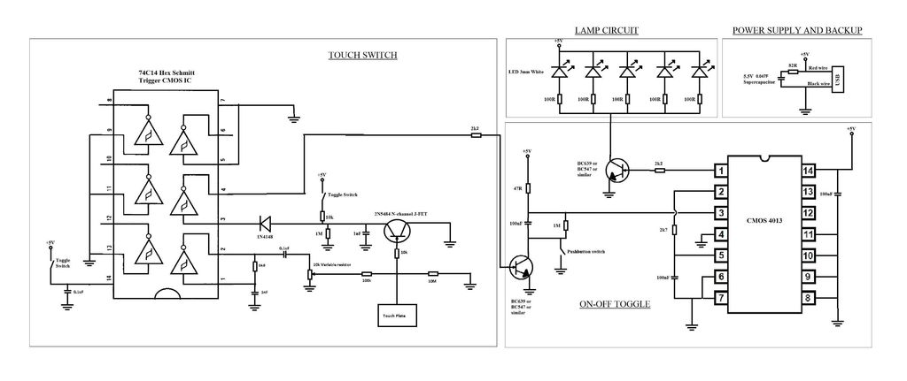
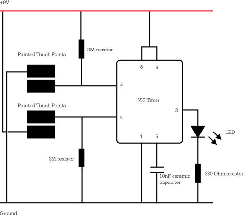
A touch switch for a USB-powered desk lamp is malfunctioning. The circuit diagram, layout, and pictures are provided below. The design incorporates circuits sourced from two websites, specifically the fourth circuit. The output of the touch switch is connected...
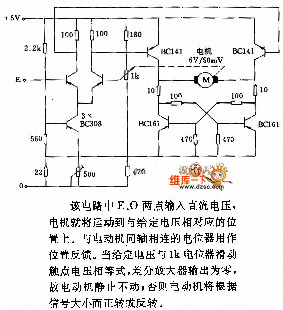
In the circuit, when E and O are input DC voltages, the motor moves to a position corresponding to the voltage. A potentiometer, coaxially connected to the motor, is used for position feedback. When the given voltage equals the...
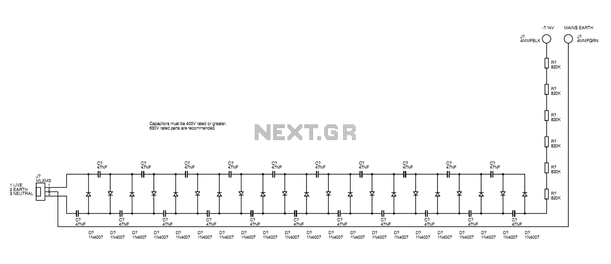
A basic mains driven Cockroft ladder high voltage generator is shown in the schematic. This is functionally the same as a project in Electronics Today International many years ago. The peak mains voltage of 340V appears across each capacitor...