
Low Power Audio Amplifier

The circuit primarily consists of an operational amplifier (op-amp) configured for audio amplification. The input signal is fed into the non-inverting terminal of the op-amp, while the feedback network between pins 1 and 8 determines the overall gain of the amplifier. The use of a 10µF capacitor in conjunction with resistors allows for flexible gain settings, enabling the user to customize the amplification level according to the specific requirements of the application.
For applications requiring a gain of 20X, the circuit can be directly used without additional components between pins 1 and 8. To achieve higher gains, the 10µF capacitor is essential, as it provides the necessary feedback capacitance to stabilize the gain at 200X. The addition of a resistor in series with the capacitor facilitates the adjustment of gain, allowing for a range of amplification from 20X to 200X, depending on the resistor value chosen.
The circuit is suitable for various audio applications, including driving small speakers in consumer electronics or DIY projects. It is important to ensure that the power supply voltage to the op-amp is appropriate for the intended output levels to prevent distortion. Additionally, care should be taken to match the speaker impedance with the output characteristics of the amplifier to avoid damage to the components. Proper layout and grounding practices should be observed to minimize noise and ensure optimal performance of the circuit.Another super-simple circuit. You could use this circuit to drive a low power speaker from a sound effects module or a noise generator. Or you could build your own amplified speakers for use with your computer. As shown (with no gain setting network between pins 1 and 8) the circuit amplifies the input signal by 20X.
A gain of 200X can be obtained by connecting a 10uF capacitor between pins 1 and 8. Connect a resistor in series with the 10uF capacitor for intermediate gain values. A 1. 2K series resistor, for example, results in a gain of 50X. 🔗 External reference
Related Circuits
A typical RF amplifier is utilized in an AM radio receiver. In the schematic, the input circuit consists of the radio's antenna (L1, a coil), which is part of an LC circuit tuned to the desired station using a...
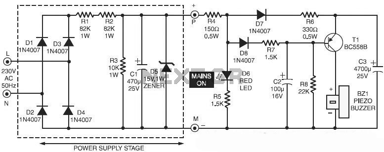
This is a specialized circuit design for a power supply failure alarm. Most power supply failure alarm or indicator circuits require an independent power supply. However, the alarm circuit presented here... The power supply failure alarm circuit is designed to...
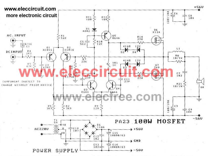
This circuit is a MOSFET power amplifier configured in an OCL (Output Capacitor-Less) topology. It delivers an output power of 100 watts and can utilize MOSFETs such as K134 and J49 or J162 and K1058. When driving an 8-ohm...
The EDFET drives like a FET, but with the bias stability of bipolar. Amps of output current can be controlled by milliamps of input current. The current gain is a design choice dictated by bandwidth. Two of things you...
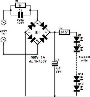
An array of white LEDs can serve as a compact lamp for living spaces. These LED lamps are commercially available and resemble standard halogen lamps, fitting into typical 230-V light fixtures. Upon inspection, it is evident that a capacitor...
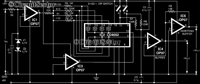
This circuit is a precision amplifier with digital control, designed for signal conditioning of low-output transducers operating in the millivolt range. The resistors R3 to R6 can be user-selected, with values ranging from 1 kilo-ohm to 1 mega-ohm, allowing...