
Low power regulator reference

The described voltage reference circuit is designed to deliver a consistent output voltage while minimizing the influence of fluctuations in the supply voltage, a characteristic referred to as power supply rejection ratio (PSRR). A PSRR exceeding 100 dB indicates that the circuit is highly effective at filtering out noise and variations from the power supply, ensuring that the output voltage remains stable under varying load conditions.
The circuit typically employs a bandgap reference or a zener diode to establish a stable reference voltage. The use of op-amps can further enhance the performance by buffering the output, providing additional isolation from load variations. Key components may include resistors for setting gain, capacitors for filtering, and possibly a voltage regulator to maintain output stability.
In practical applications, this type of voltage reference circuit is crucial for precision analog circuits, such as analog-to-digital converters (ADCs) and digital-to-analog converters (DACs), where stable reference voltages are necessary for accurate signal processing. The high PSRR allows the circuit to function effectively in environments with significant electrical noise, making it suitable for use in industrial and consumer electronics where power supply variations are common.
Design considerations include the selection of components that can withstand the expected range of operating conditions, as well as thermal stability to ensure that the reference voltage does not drift with temperature changes. Overall, this voltage reference circuit is an essential building block in the design of reliable electronic systems.This simple reference circuit provides a stable voltage reference almost totally free of supply voltage hash Typical power supply rejection exceeds 100 dB.
Related Circuits
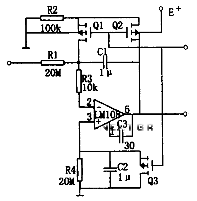
The integrator drift is minimal, not exceeding 500 V/s within the temperature range of -55°C to +125°C, as illustrated in the figure. The basic integrator is comprised of an operational amplifier, resistor R1, and capacitor C1. To enhance the...
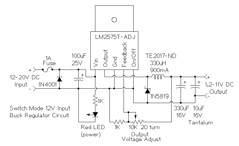
This is a simple buck mode switching regulator circuit diagram. This circuit is more efficient; switch mode regulators convert DC input voltage to pulses of high DC voltage. The DC pulses are used to charge a storage capacitor to...
A compact and portable 12V solar power inverter circuit designed to provide illumination. This proven design converts 12V DC from a storage battery. This 12V solar power inverter circuit is engineered to transform direct current (DC) from a solar battery...
Integrated AF power amplifiers have experienced significant advancements in recent years, offering enhanced power and ease of use. The TDA1519C from Philips features two power amplifiers that provide 11 W per channel in stereo mode or 22 W in...
The LM317 is an adjustable, positive 3-terminal voltage regulator capable of supplying 100 mA (for RA87U control) or 1.5 A (for Order Code UF27E and N61CA) across an output voltage range of 1.2 V to 37 V. These voltage...
This article addresses inquiries regarding a low-power FM transmitter designed to accept input from various sound sources, such as a guitar or microphone, and transmit on the commercial FM band. It is important to select an unused frequency on...