
Low-Power Voltage Doubler (Booster)
")
Miniature electronic devices, which include a wide range of applications from portable gadgets to remote sensors, typically rely on battery power for operation. However, many of these devices necessitate voltages that exceed the nominal levels provided by standard batteries. This requirement can be addressed through various methods, such as using a boost converter circuit.
A boost converter is a DC-DC converter that steps up the input voltage to a higher output voltage, making it suitable for powering devices that require more energy than is available from the battery source. The basic operation of a boost converter involves an inductor, a switch (usually a transistor), a diode, and a capacitor.
When the switch is closed, current flows through the inductor, storing energy in its magnetic field. Once the switch opens, the energy stored in the inductor is released, causing the voltage to increase due to the collapsing magnetic field. The diode prevents the current from flowing back into the switch, directing it instead to the output capacitor, which smooths out the voltage to provide a stable output.
The design of the boost converter must consider factors such as the input voltage range, desired output voltage, load current, and efficiency. Additionally, feedback control mechanisms are often implemented to regulate the output voltage, ensuring that it remains stable despite variations in load or input voltage.
In summary, the integration of a boost converter into miniature electronic devices allows them to efficiently utilize battery power while meeting the higher voltage requirements necessary for optimal performance. This capability is pivotal in extending the functionality and longevity of portable electronic applications.All miniature electronic devices operate off batteries. Some of them need higher than the standard battery voltages to operate efficiently. If the battery.. 🔗 External reference
Related Circuits
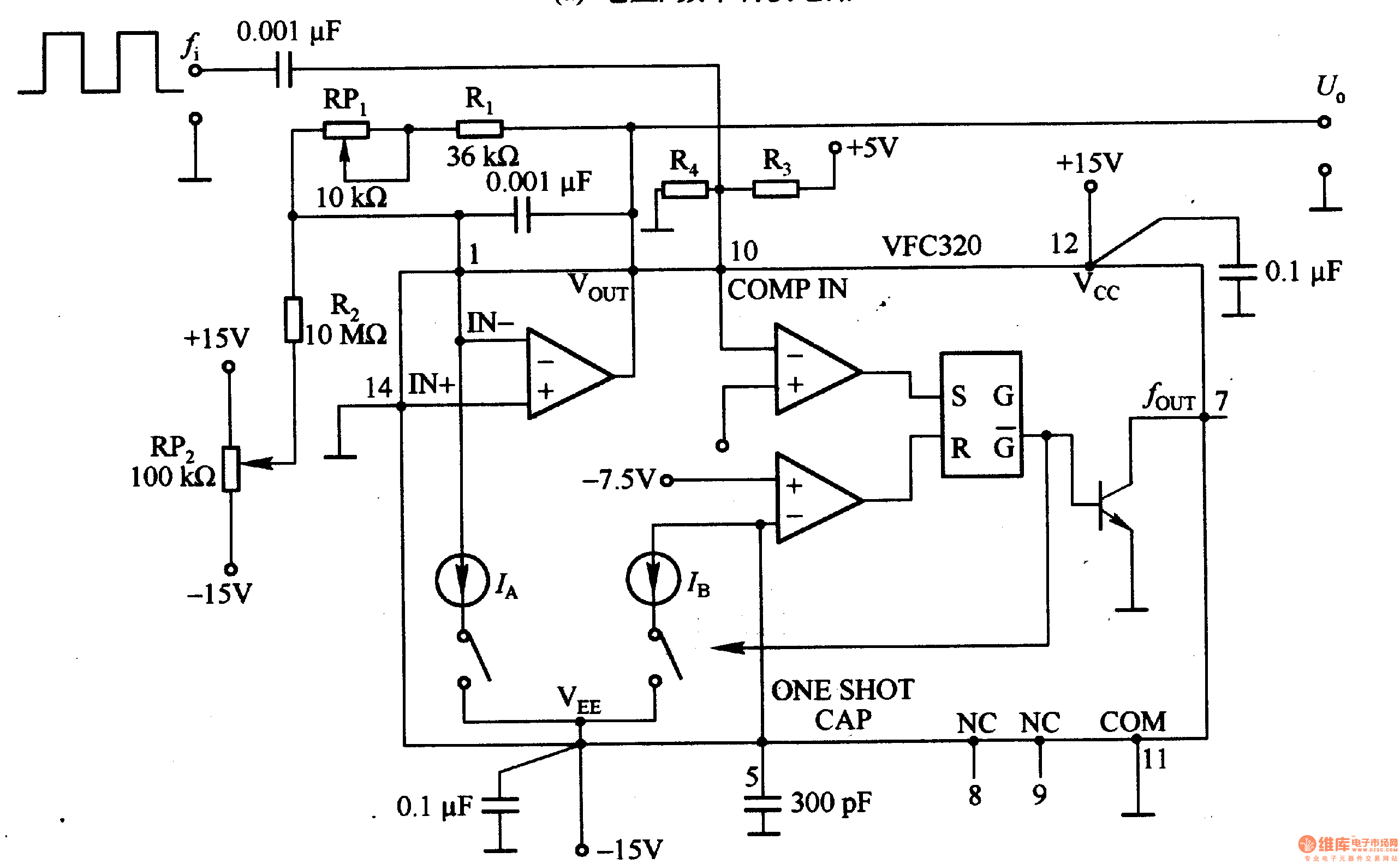
Figure 1-22 (a) illustrates a circuit that converts an input voltage of 0 to +10V (Ui) into a pulse with an output frequency ranging from 0 to 100kHz. In this configuration, pin 7 of the VFC320 is connected to...
This circuit is designed to demonstrate high-frequency high voltage, capable of producing voltages up to approximately 30 kV, depending on the transformer used. It is economical and straightforward to construct, primarily utilizing a standard TV flyback transformer. The circuit...
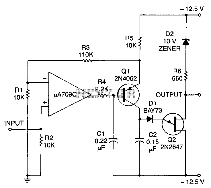
This circuit consists of a UJT oscillator where the timing charge capacitor C2 is linearly dependent on the input signal voltage. The charging current is determined by the voltage across resistor R5, which is precisely controlled by the amplifier....
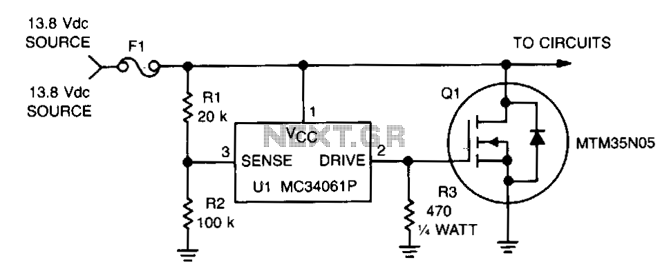
This circuit protects expensive portable equipment against all types of improper hookups and environmental hazards that could cause an overvoltage condition. It operates very quickly and does not latch up; rather, it recovers when the overvoltage condition is removed....
The LM317 is capable of providing extremely good load regulation, but a few precautions are needed to obtain maximum performance. For best performance, the programming resistor (R1) should be connected as close to the regulator as possible to minimize...

Voltage variations and power cuts adversely affect various equipment such as TVs, VCRs, music systems, and refrigerators. This simple circuit will protect costly equipment from high and low voltages and voltage surges when power resumes. It also produces a...