
Low Voltage High Current Time Delay Circuit

The circuit under discussion employs the LM339, a quad comparator known for its ability to operate in low voltage conditions while providing reliable performance. The configuration of three comparators in parallel enhances the current-driving capability, allowing the circuit to effectively control high power loads. The PNP transistor (2N2905) acts as an intermediary switch, amplifying the output from the comparators to drive the TIP35 NPN transistor, which is capable of handling significant current loads.
The fourth comparator's role in generating a time delay is crucial for applications requiring controlled timing sequences. The voltage divider composed of 36K and 62K resistors ensures that the voltage at the comparator’s positive input is set correctly, allowing for precise timing control. The choice of a 50µF capacitor paired with a 100K variable resistor provides flexibility in adjusting the time delay, making the circuit adaptable to various applications.
For users needing to adjust the timing, the variable resistor allows for fine-tuning of the delay period. Reducing the resistance will shorten the delay, while increasing it will lengthen the timing. The capacitor's value also plays a significant role in this timing equation, where smaller capacitors will yield shorter delays and larger capacitors will extend the delay period.
In scenarios where the circuit is required to operate at higher voltages, careful consideration must be given to the 10-ohm resistor, as it must be increased to maintain circuit stability and performance. This proportional adjustment ensures that the current remains within safe limits, preventing damage to the components while optimizing the circuit's functionality. Overall, this design exemplifies a versatile approach to timing and current control using readily available components.In this circuit a LM339 quad voltage comparator is used to generate a time delay and control a high current output at low voltage. Approximatey 5 amps of current can be obtained using a couple fresh alkaline D batteries. Three of the comparators are wired in parallel to drive a medium power PNP transistor (2N2905 or similar) which in turn drives a
high current NPN transistor (TIP35 or similar). The 4th comparator is used to generate a time delay after the normally closed switch is opened. Two resistors (36K and 62K) are used as a voltage divider which applies about two-thirds of the battery voltage to the (+) comparator input, or about 2 volts. The delay time after the switch is opened will be around one time constant using a 50uF capacitor and 100K variable resistor, or about (50u * 100K) = 5 seconds.
The time can be reduced by adjusting the resistor to a lower value or using a smaller capacitor. Longer times can be obtained with a larger resistor or capacitor. To operate the circuit on higher voltages, the 10 ohm resistor should be increased proportionally, (4. 5 volts = 15 ohms). 🔗 External reference
Related Circuits
Instructions for creating a Clap-Clap On/Clap-Clap Off switch circuit. This guide provides the necessary information for constructing a clap-activated switch. The Clap-Clap switch circuit is an innovative design that utilizes sound activation to control electronic devices. The primary components of...
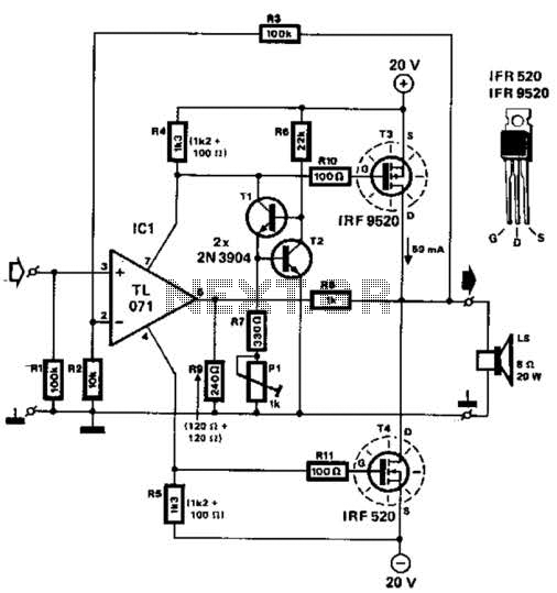
Two complementary MOSFETs are utilized to deliver 20 W into an 8-ohm load. A TL071 operational amplifier serves as the input amplifier. The MOSFETs must be equipped with a heatsink that has a thermal resistance of better than 5...
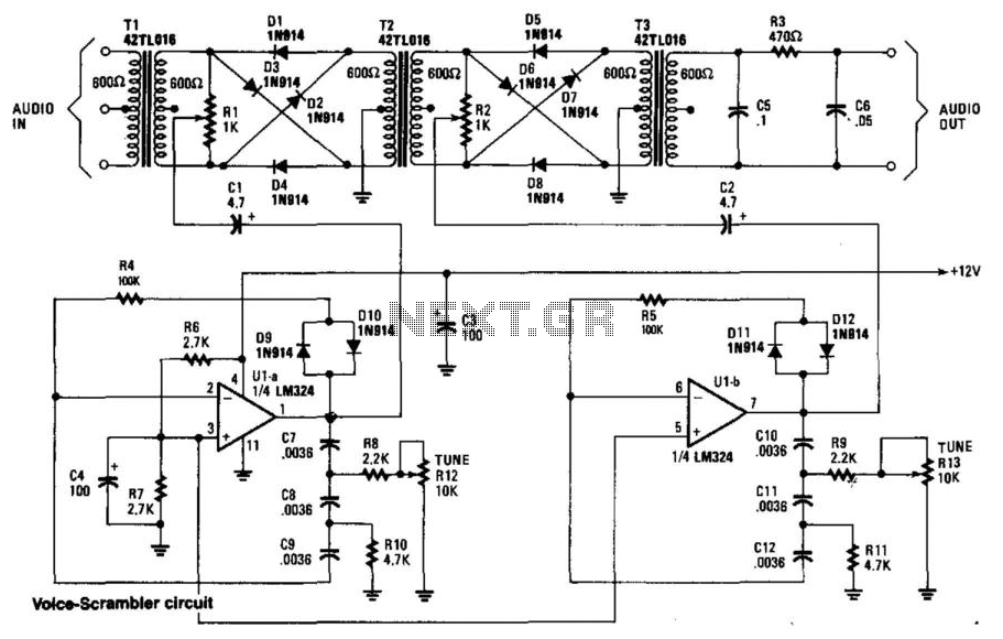
This circuit employs two balanced modulators to generate a Double Sideband (DSB) signal, followed by the reinsertion of a carrier frequency that differs from the original. This alteration leads to distortion of the input signal. While a voice signal...
The hum noise is produced by an electronic device with improper design. To address this issue, it is essential to identify the source of the hum. This involves checking the grounding, cabling, casing, and other factors that may contribute...
The following circuit illustrates an Ultrasonic Sensor Switch circuit diagram. This circuit is based on the 555 Timer IC for the Ultrasonic Transmitter. The Ultrasonic Sensor Switch circuit utilizes a 555 Timer IC configured in astable mode to generate ultrasonic...
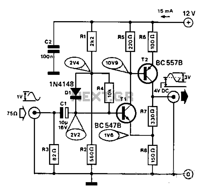
Commonly used for cameras or computers with black and white television connections, the amplifier has a gain of 3 and a bandwidth of 10 MHz. The described circuit is an amplifier designed for applications involving cameras or computers that interface...