
Lowpass filter uses only two values

The composite lowpass filter is a sophisticated electronic circuit designed to allow signals below a certain cutoff frequency to pass while attenuating higher-frequency signals. The architecture of this filter is based on the constant-k design, which employs full sections of the filter that are characterized by a specific transmission line configuration. These sections are then terminated with m-derived half-sections, which enhance the filter's performance by improving its frequency response and minimizing ripple in the passband.
In the design, two distinct values of inductors and capacitors are utilized, which allows for fine-tuning of the filter's characteristics, such as the cutoff frequency and the quality factor (Q). The use of four inductors and five capacitors in the first schematic (Figure 1) indicates a balanced approach to achieving the desired filter response, while the second schematic (Figure 2) demonstrates an alternative design that incorporates eight inductors and 14 capacitors of a single value. This configuration suggests a more complex filter arrangement that could provide sharper roll-off characteristics and improved selectivity.
The combination of series, parallel, and series-parallel connections in the filter design allows for greater flexibility in achieving the desired electrical characteristics. Series connections typically increase the overall impedance, while parallel connections reduce it, allowing for careful manipulation of the filter's input and output characteristics. The judicious selection and arrangement of these components are critical in achieving optimal performance, particularly in applications requiring precise filtering of signal frequencies.
In practical applications, such composite lowpass filters are widely used in communication systems, audio processing, and signal conditioning, where the elimination of unwanted high-frequency noise is essential for maintaining signal integrity. The design techniques employed in these filters can also be adapted for highpass and wideband filters, making them versatile tools in the engineer's arsenal for managing frequency response in various electronic systems.The composite lowpass filter uses interior constant-k full sections terminated by m-derived half-sections.The design technique is also applicable to highpass and wideband filters (references 3 and 4). Figure 1 shows a schematic of the composite lowpass filter. The filter uses four inductors of two different values and five capacitors of two different values. Figure 2 shows the schematic of an equivalent composite lowpass filter. This filter uses judicious combinations of components in series, parallel, and series-parallel. The filter uses eight inductors and 14 capacitors of only one value each. 🔗 External reference
Related Circuits
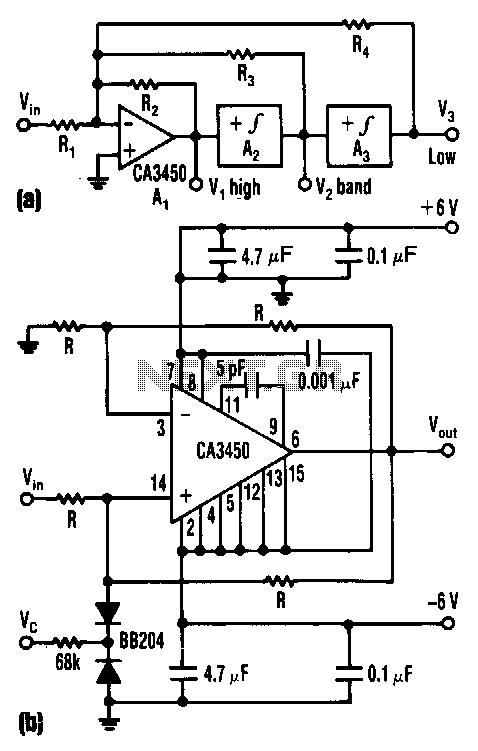
The control voltage Vc effectively adjusts the cutoff frequency w0 of this state-variable filter to any desired value, ranging from approximately 1.7 MHz to 5 MHz, using a BB 204 varicap and a resistance of 100 kΩ. Vc can...
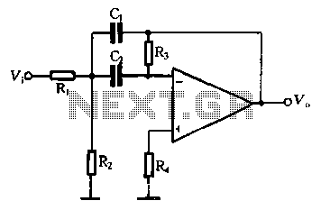
The performance of a second-order band-pass filter is primarily influenced by the quality factor (Q) and the center frequency (Si). To adjust the Q value, R3 should be modified first, followed by adjustments to C0. However, these adjustments will...
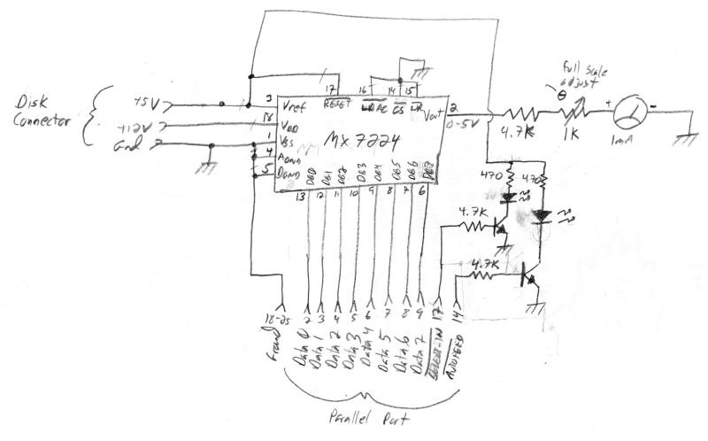
The meter was acquired from eBay and features a full-scale movement of 1 mA, already marked from 0 to 100. The original scale was removed, scanned, and modified to include "% NETWORK" markings using an image editor. The new...
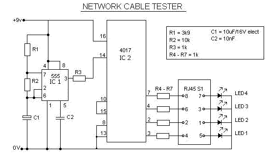
This is a multifunction RJ45 network cable tester designed for testing network cables (RJ45) and telephone cables (RJ11). It is cost-effective and user-friendly. The tester determines whether a network cable is a crossover or straight type by illuminating a...
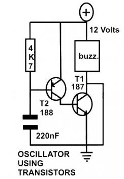
This schematic diagram represents a basic oscillator circuit utilizing two transistors. When the transistors and several passive components are connected as illustrated, the circuit begins to oscillate. The oscillation frequency can be modified by altering the values of either...
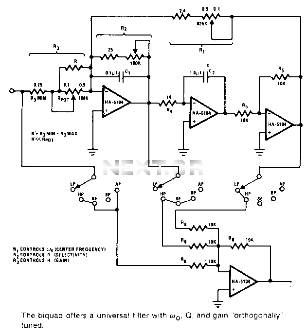
This universal filter provides low-pass, high-pass, bandpass, band elimination, and all-pass functions. The Biquad consists of two successive integration stages followed by an inverting stage. The entire system features a feedback loop from the front to the back, primarily...