
Active bandpass filter principle

The second-order band-pass filter is a critical component in various electronic applications, particularly in signal processing where specific frequency ranges need to be isolated. The design of this filter centers around the quality factor (Q), which defines the filter's selectivity and bandwidth. A higher Q value indicates a narrower bandwidth and greater selectivity, but it also poses challenges such as increased sensitivity to component tolerances and potential signal attenuation.
In practical implementations, the adjustment of R3 affects the Q factor directly. Increasing R3 raises the Q value, enhancing selectivity but also risking excessive attenuation of the input signal. Conversely, reducing R3 lowers the Q factor, broadening the bandwidth and potentially allowing more of the input signal to pass through. The capacitor C0 also plays a pivotal role in determining the filter's center frequency (Si) and must be adjusted in conjunction with R3 to maintain the desired performance characteristics.
The theoretical foundation of the filter's operation can be illustrated using an operational amplifier (op-amp) configuration. The inverting terminal's DC resistance, when grounded, establishes a feedback loop that stabilizes the filter's response. The relationship between R3 and R4 is crucial, as they must be matched to ensure optimal performance. The design suggests that for effective operation, R4 should equal R3, creating a balanced circuit that adheres to the principles of equality in feedback networks.
The maximum allowable Q value of 20 should be approached cautiously, as exceeding this threshold can lead to undesirable effects such as increased noise and distortion. The recommendation of a Q value around 10 strikes a balance between selectivity and stability, making it suitable for most applications. Additionally, the maximum transmission ratio (KF) should be carefully selected based on the specific requirements of the application, with a value around 10 being optimal for amplifiers with adjustable gain.
To finalize the design, the values of R1, R3, C, and R4 need to be calculated based on the desired Q, center frequency (fo), and transmission ratio (KF). This ensures that the second-order band-pass filter meets the necessary specifications for its intended application, providing reliable and effective signal processing capabilities.Second order band-pass filter performance depends primarily on the quality factor Q and center frequency Si. In order to adjust the Q and. t a general first adjust R3 to change the Q value, and then adjust to change C 0. But the adjustment will affect R3 Si. Figure R4 and Si-independent, so that the capacitor C is now open, according to the same phase-inverting terminal of the operational amplifier to ground the DC resistance of the principles of equality, availability R4 = R3 = R3. Second order bandpass filter the Q value of the maximum undeclared more than 20, and generally 10 is appropriate, Q values of the election was high, resistance is 2 feet lower bound value, so the input signal will be severely attenuated, and to increase the amplifier burden.
Since the Q value of the parameter element number of errors is very sensitive in general to 0 10 appropriate. KF is the maximum transmission ratio can range from 1 ^ f100 select within, if the display driver stage amplifier with an adjustable gain, the band-pass filter 10 to take appropriate din KF.
In determining the value of Q, fo KF and after, can be obtained in the filter R l, R R 3, C and R4 of value.
Related Circuits
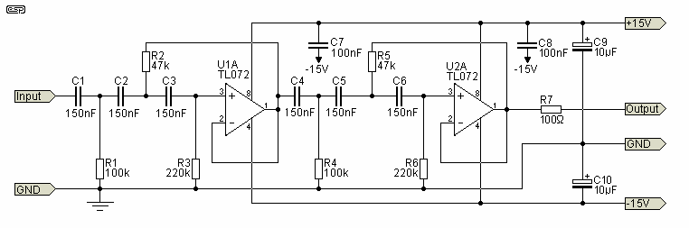
The circuit shown is completely conventional. The Q of the filters has been optimized to allow a higher input impedance than would otherwise be possible, with the final Q of the two filters being almost exactly 0.707 (i.e., a...
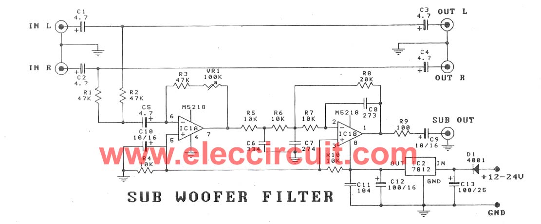
This subwoofer filter set is suitable for use with a high-quality car audio system. The circuit is designed to operate with a 12-volt DC power supply. The subwoofer filter set serves as an essential component in enhancing the audio experience...
Electronics tutorial about active band-pass filters, including band-pass filter frequency response, its resonant frequency, and second-order response. Active band-pass filters are essential components in various electronic applications, particularly in signal processing, audio engineering, and communications. These filters are designed to...
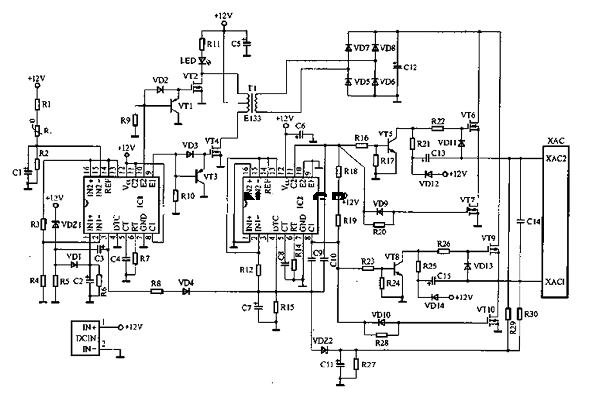
A common car inverter circuit and its working principle. Car inverter specifications include: Input voltage: DC 10V to 14.5V; Output voltage: AC 200V to 220V with a tolerance of 10%; Output frequency: 50Hz with a tolerance of 5%; Output...
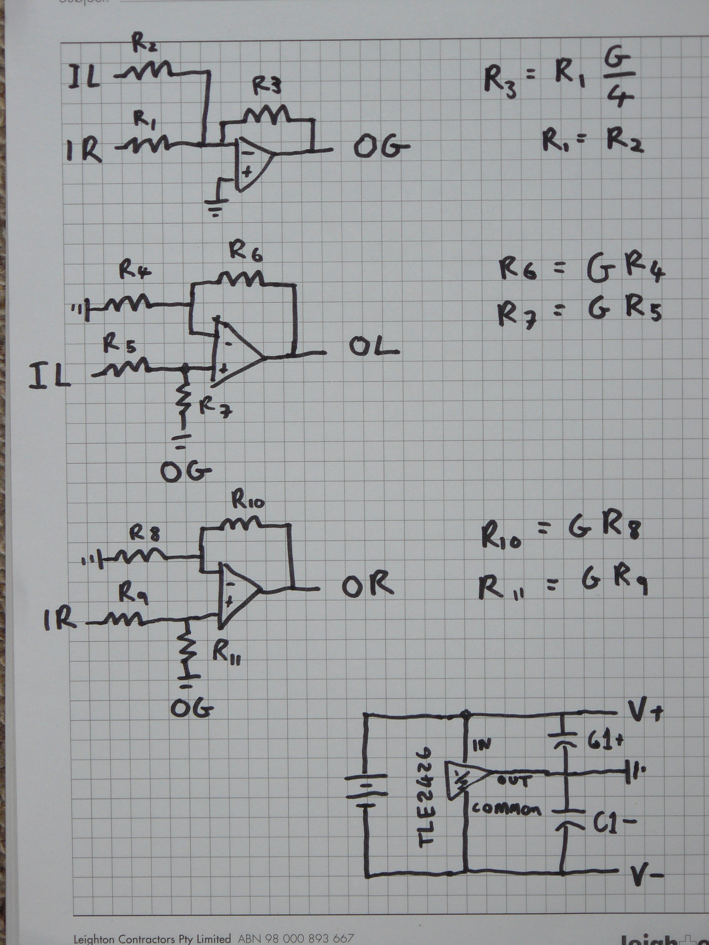
The design aims for a higher output voltage swing for the mono part of the signal. There is skepticism regarding the proposed method due to potential crosstalk issues unless resistors are precisely matched. A schematic was planned where G...
A schematic diagram for a broadband QRP SWR metering circuit intended for use in a QRP antenna tuner. The circuit allows the user to press a momentary DPDT switch to observe an LED indicator while adjusting the capacitors of...