
LTC1045 TTL RS-232 Converter
The RS-232 standard is widely used for serial communication, and it operates at voltage levels that are not directly compatible with TTL logic levels used in most digital circuits. The proposed circuit effectively bridges this gap by converting the higher voltage RS-232 signals (typically ranging from -15V to +15V) to TTL levels (0V to +5V).
The circuit typically includes a level shifter, which can be implemented using a combination of transistors or dedicated ICs designed for this purpose, such as the MAX232. The MAX232 is a popular choice as it contains built-in charge pumps that generate the required voltage levels for RS-232 communication while providing the necessary signal inversion.
The circuit layout would include an RS-232 connector, which connects to the serial data source, and a TTL output that interfaces with microcontrollers or other digital logic devices. Proper decoupling capacitors should be included close to the power supply pins of the level shifter to ensure stable operation. Additionally, the circuit may feature protection diodes to safeguard against voltage spikes or incorrect connections.
Powering the circuit from batteries allows for portable applications, making it ideal for remote data acquisition systems or mobile devices that require serial communication without being tethered to a power outlet. The design should also consider power efficiency to prolong battery life, which can involve using low-power components and optimizing the circuit layout.
In summary, this simple battery-powered RS-232 receiver circuit is an essential tool for interfacing RS-232 communication with TTL logic, enabling a wide range of applications in electronics and embedded systems.A simple way to build a battery-powered RS-232 receiver circuit is shown on the following schematic diagram. This circuit convert RS232 level to TTL level.. 🔗 External reference
Related Circuits
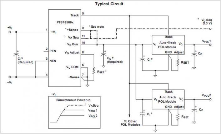
PTB78560BAS is a subpackage of PTB78560B. For a detailed description, please refer to PTB78560B. The datasheet for PTB78560BAS can be downloaded below. Provided by Texas Instruments. The PTB78560BAS is a specific variant within the PTB78560B family of components, designed for...
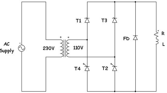
Controlled rectifiers are line-commutated AC to DC power converters that convert a fixed voltage and fixed frequency AC power supply into a variable DC output voltage. The input supply provided to a controlled rectifier is an AC supply with...
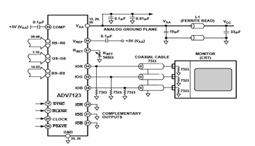
This digital-to-analog converter (DAC) integrated circuit is designed for optimal noise performance, minimizing both radiated and conducted noise. A recommended connection diagram for the ADV7123 is depicted in the following schematic diagram. According to the ADV7123 datasheet, this device...
There are many individuals interested in listening to frequencies within the VHF range of 108 to 132 MHz. This VHF AM converter is designed to convert signals from a frequency band of 106 to 150 MHz, allowing users to...
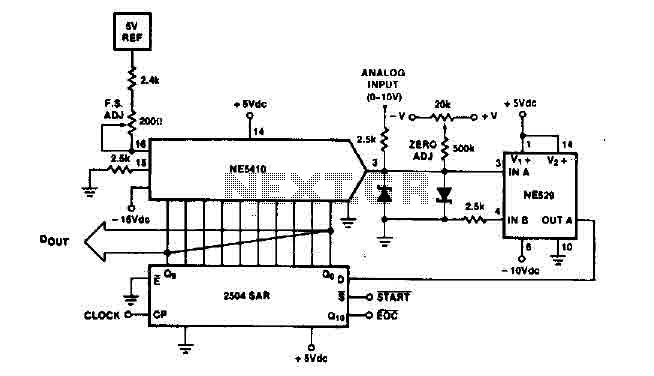
The time IO-bit conversion operates at 3.3 MHz with a clock signal. This converter utilizes a 2504 12-bit register in successive approximation mode, where the conversion signal for the short-cycle end is derived from the first bit utilized in...
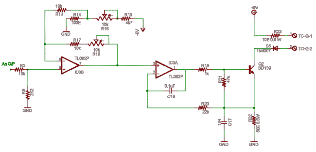
Ensure a ±5V dual supply for the TL062 operational amplifier (IC3). The ground is shared as the power supply ground, allowing grounds to radiate from the ground plane on one side of the PCB. Resistors R3-R8 form an attenuator...
Warning: include(partials/cookie-banner.php): Failed to open stream: Permission denied in /var/www/html/nextgr/view-circuit.php on line 713
Warning: include(): Failed opening 'partials/cookie-banner.php' for inclusion (include_path='.:/usr/share/php') in /var/www/html/nextgr/view-circuit.php on line 713