
VHF to AM Converter Circuit

The VHF AM converter circuit is designed to receive signals in the specified frequency range and convert them to a more manageable frequency for further processing or listening. The core components of this circuit typically include a radio frequency (RF) amplifier, a mixer, and a local oscillator (LO).
The RF amplifier boosts the incoming VHF signals, which may be weak due to distance or interference. Following amplification, the signals are fed into a mixer. The mixer combines the amplified VHF signal with a local oscillator signal, generating intermediate frequencies (IF) that fall within a more convenient range for demodulation. The choice of the local oscillator frequency is crucial, as it determines the output frequency of the mixer.
In addition to these components, the circuit may include filters to eliminate unwanted signals and noise, ensuring that only the desired frequencies are processed. A demodulator is used to extract the audio information from the converted RF signals, allowing users to listen to the transmissions.
Power supply considerations for the circuit are also important, as the components require stable voltage levels for optimal performance. The design may include voltage regulators to ensure that each part of the circuit receives the appropriate voltage.
Overall, the VHF AM converter is a valuable tool for enthusiasts and professionals alike, enabling access to a range of VHF communications, including aviation, marine, and amateur radio transmissions.There are many people who want to listen whats going on in VHF 108 - 132 MHz. This vhf am converter converts a band between 106 and 150 MHz, so you can lis.. 🔗 External reference
Related Circuits

This circuit is a touch switch circuit, similar to a touch door alarm. It utilizes a 555 timer as the core component of the touch switch circuit. The operation begins when the plate is touched, triggering the 555 timer....
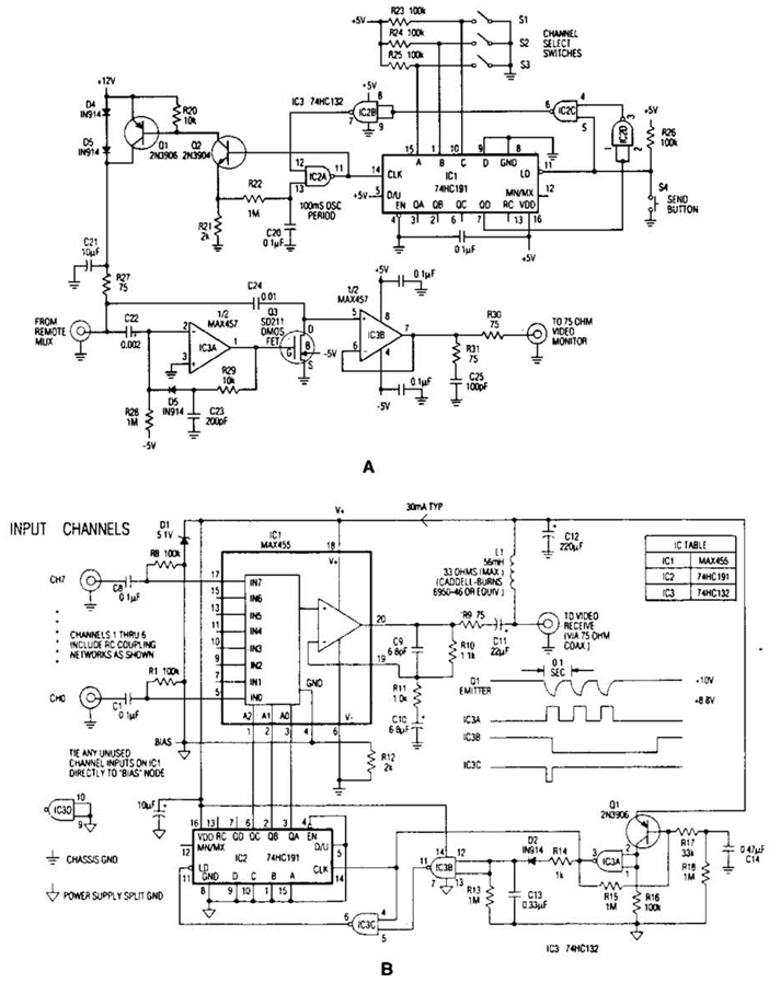
In the video system shown in Figs. A and R, a single coaxial cable transmits power to a remote location, selects one of eight video channels, and returns the chosen signal. This system can select from multiple remote surveillance...
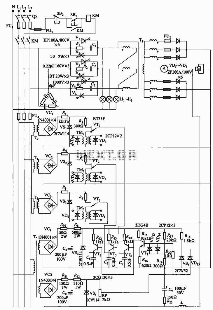
The 300A-18V three-phase thyristor power regulator circuit is designed for electrolysis applications. It can output a direct current of 3000A at an adjustable voltage of 18V, providing a power supply solution for various processing needs. The circuit comprises a...
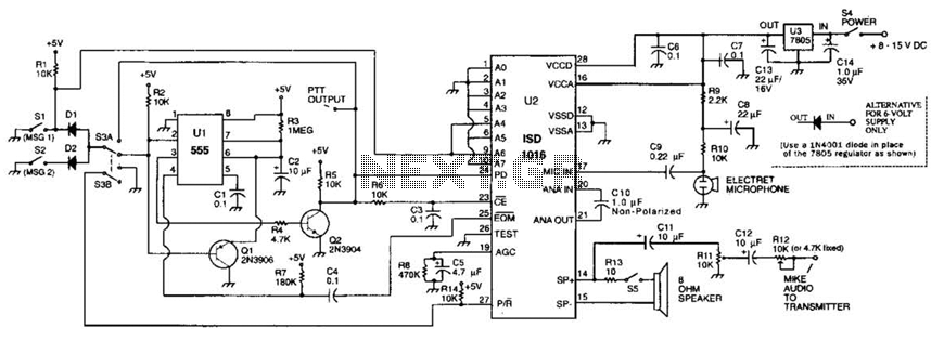
The circuit utilizes an ISD1016 audio record/playback chip from Information Storage Devices, Inc. to record and playback messages on demand. While it is primarily designed for use with transmitters, it can also serve as an electronic notepad or similar...
The circuit is a bell timer. This project utilizes the AT89S52 microcontroller and an I2C EEPROM for storing alarm timings. Additionally, the 7-segment display has been replaced with an LCD display. The DS1307 is employed for real-time clock functionality....

The automatic emergency light circuit has the following features: 1. When the mains supply (230V AC) is available, it charges a 12V battery up to 13.5V, after which the battery is disconnected from the charging section. 2. When the...