
LV8741V PWM stepping motor driver electronic project circuit design

This PWM current-control stepping motor driver circuit is designed to effectively manage the operation of a DC motor by modulating the power supplied to the motor based on pulse-width modulation (PWM) techniques. The core functionality of the integrated circuit (IC) is to provide precise control over the motor's speed and torque by adjusting the duty cycle of the PWM signal.
The maximum output current rating of 1.5 amperes indicates that this driver can handle a range of small to medium-sized motors, making it suitable for various applications in robotics, automation, and hobby projects. The incorporation of an auto recovery-type short-circuit protection mechanism (EMM = Low) ensures that the circuit can recover from fault conditions without manual intervention, enhancing reliability and safety during operation.
The output enable function (OE = High) keeps the output continuously enabled, allowing for immediate response when the circuit is powered on. This feature is crucial in applications where motor operation must commence without delay. The current limit reference voltage setting at 100% (ATT1 = Low, ATT2 = Low) ensures that the motor operates within safe current limits, preventing damage due to overcurrent conditions.
The chopping frequency of 37 kHz, determined by the resistor value (RCHOP = 43 kΩ), is critical for minimizing audible noise and ensuring smooth motor operation. This frequency is typically chosen to balance the need for efficient motor control with the avoidance of excessive electromagnetic interference and heat generation.
In summary, this PWM current-control stepping motor driver circuit is a well-designed solution for controlling DC motors, featuring essential protection mechanisms, reliable operational characteristics, and flexible configuration options to suit various applications.As you can see in the circuit diagram, this electronic project require few external electronic parts. The maximum output current that can be provided by this PWM current-control stepping motor driver IC is up to 1.
5 ampere. The setting conditions for the above PWM current-control DC motor driver circuit diagram are as follows : Auto recovery-ty pe output short-circuit protection function (EMM = Low), Output enable function fixed to output ON state (OE = High), Current limit reference voltage setting = 100% (ATT1 = Low, ATT2 = Low), Chopping frequency : 37kHz (RCHOP = 43k ). 🔗 External reference
Related Circuits
An individual has been studying Nikola Tesla's work for approximately 11 months and recently discovered Imhotep's concept of Radiant energy. The study of Nikola Tesla's contributions to electrical engineering and energy transmission has led to significant advancements in understanding electromagnetic...
Under the loading condition of the resistance, the output voltage (Uo) variable range is from 30V to 36V, with a maximum output current (Imax) of 2A. When the input voltage (U2) changes from 15V to 21V, the voltage regulation...
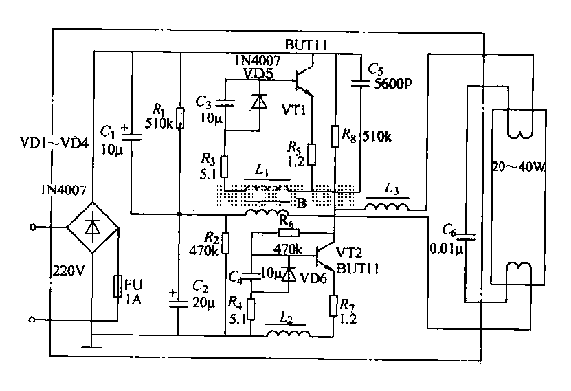
Electronic ballasts operate over a wide voltage range, provide fast startup with no noise or flicker, and contribute to energy savings. Their acceptance among users has been increasing. The circuit depicted in the figure represents a typical electronic ballast...
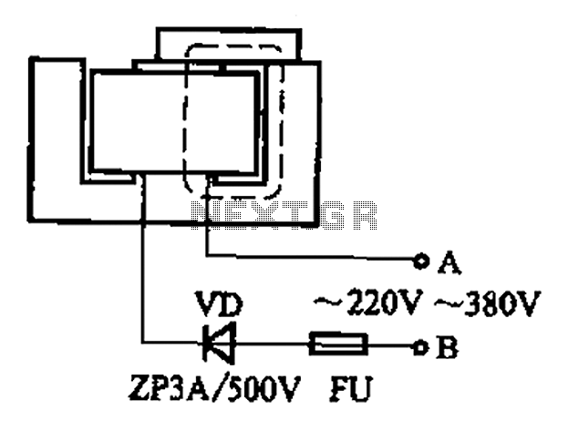
After some minor loss of field magnets, they can be re-magnetized using a homemade method. A scrap of exchanges and contacts, as well as other models like CJ10-60 ~ 15, can be utilized. The circuit operates at 0A (compatible...
The circuit indicates two different water temperature trip points by activating LEDs when the specified temperatures are reached. It is built around the LM2904 dual operational amplifier, which is powered by a 12 V automotive system. A thermistor is...
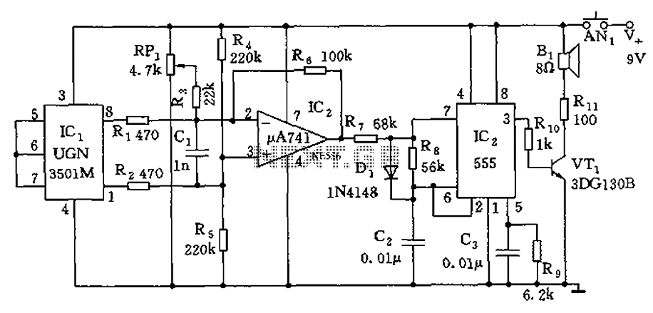
The circuit consists of a 555 timer and associated components designed for voltage-to-frequency conversion. It is utilized for determining the orientation of Earth's magnetic field using a Hall-effect sensor, specifically the UGN-3501M. This sensor incorporates a Hall element and...