
Car temperature indicator circuit

The described circuit is a temperature monitoring system that utilizes the LM2904 dual operational amplifier to provide visual alerts through LEDs when specific water temperature thresholds are reached. The operational amplifier configuration allows for precise voltage comparisons between the thermistor input and the reference voltages set by the resistive components.
The thermistor, a temperature-sensitive resistor, decreases its resistance as temperature rises. This characteristic allows it to act as a variable resistor in the voltage divider configuration with the 10 kΩ resistor. The voltage at the non-inverting inputs of the LM2904 will vary inversely with the thermistor's resistance, enabling the circuit to detect temperature changes effectively.
The reference voltage for the inverting inputs is established by the combination of a fixed 10 kΩ resistor and a variable 2 kΩ potentiometer. This arrangement allows for fine-tuning of the trip points, facilitating calibration to specific temperature thresholds required for the application. The use of a potentiometer provides an adjustable method to set the desired trip points without the need for replacing components.
When the voltage at the non-inverting input surpasses the threshold set at the inverting input, the output of the operational amplifier changes state, causing the TIL220 LED to turn on. This visual indication serves as an alert that the water temperature has reached or exceeded the pre-set limit.
For enhanced functionality, the circuit can be expanded to include additional components such as relays or motor drivers. This capability allows for the integration of automatic control systems, such as activating cooling fans or pumps, which can be beneficial in managing temperature-sensitive processes or environments.
Overall, this circuit design is efficient for monitoring temperature thresholds and provides a flexible platform for various applications in automotive or industrial settings.The circuit is used to indicate two different water temperature trip points by turning on LEDs when the temperatures are reached. The circuit is constructed around the LM2904 dual operational amplifier powered from the 12 V auto system.
The thermistor is in series with a 10 kSi resistor from ground to the positive 9.1 V point. The top of the thermistor is tied to both non-inverting inputs of the LM2904. The voltage at these inputs will change as the thermistor resistance changes with temperature. Each inverting input on the LM2904 has a reference, or threshold trip point, set by a 10 kfi resistor and a 2 kfl potentiometer in series across the 9.1 V regulated voltage. When this threshold is exceeded on the non-inverting input of LM2904, the TIL220 LED lights. The two trip points can be recalibrated or set to trip at different temperatures by adjusting the 2 k?
potentiometer in each section. In addition to being used as warning lights as shown here, circuits can be added to turn on the fan motor or activate a relay.
Related Circuits

This is a true subwoofer circuit designed specifically for 15- to 18-inch woofers and is not compatible with 6- or 8-inch subwoofers. It features a bass-reflex design. The true subwoofer circuit operates by utilizing a bass-reflex enclosure, which enhances low-frequency...

This simple circuit can create an 18 LED flasher to decorate a Christmas tree. The white, blue, and red LEDs flash at different rates to provide a colorful display. It is a light-sensitive circuit, automatically activating in the evening...
I have had a lot of queries about getting a low power negative supply in cars, to power Linkwitz transform circuits and the like. There is a switchmode converter, but I must admit that it is overkill for what...
This low-power video transmitter is designed for remote control (R/C) applications, surveillance, or amateur radio purposes. It utilizes seven transistors within a crystal oscillator-multiplier RF power amplifier chain, along with a high-level video modulator. A supply voltage of 9...

Active power factor correction stabilizes the electrical demand of a device to provide optimal power factor characteristics for various types of loads. To comply with power factor regulations, a cost-effective solution should be designed. In many applications, the requirement...
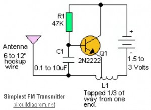
This is likely the simplest radio transmitter available, consisting of five components and capable of being assembled in a compact space. It is suitable for science fair projects or other science-related endeavors where short-range transmission is beneficial. The device...