
Machine vision illumination stabilizer

Current then decays through the lamp, L1, and D3 until the lamp voltage falls below 115 V, at which point Q1 turns OFF and the cycle repeats.
The circuit employs a hysteresis oscillator configuration, utilizing transistor Q1, Q2, and operational amplifier U1 to maintain stable illumination of a lamp. The full-wave bridge rectifier D3 converts the incoming AC voltage to unregulated DC voltage, which is essential for powering both the lamp and the associated control circuitry. The 10 V zener diode serves as a voltage reference, ensuring that the CMOS Schmitt trigger operates within its specified range, providing reliable switching behavior.
When the voltage across the lamp exceeds 115 V, Q1 is activated, allowing current to flow through charging capacitor C1 via resistor R2. This charging process increases the voltage at the input of U1A until it surpasses the threshold voltage, triggering a response from the Schmitt trigger. The output from U1C and U1D subsequently goes low, which in turn signals Q2 to turn OFF, interrupting the current flow through the lamp.
As the current through the lamp decreases, the voltage across the lamp drops. This continues until the voltage falls below the critical threshold of 115 V, at which point Q1 deactivates, and the entire process starts anew. This feedback mechanism ensures that the lamp remains illuminated at a stable brightness, preventing flickering and enhancing the longevity of the lamp by avoiding excessive voltage conditions.
The design emphasizes efficiency by utilizing components that are well-suited for the intended application, such as the CMOS technology in the Schmitt trigger for low power consumption and rapid switching capabilities. The hysteresis effect provides noise immunity, ensuring stable operation even in the presence of voltage fluctuations. Overall, this circuit exemplifies a robust solution for maintaining consistent lamp illumination in various lighting applications.The combination of Ql, Q2 and Ul form a hysteresis oscillator to stabilize lamp illumination. In operation, full wave bridge D3 operates directly from the ac line to supply unregulated dc to the lamp and also to the 10 V zener that provides power to the quad CMOS Schmitt trigger, Ul. When the lamp supply exceeds 115 V, Ql is turned ON, charging Cl through R2 to raise the input to Ula past the positive-going logic threshold.
This drops the output voltage at Ulc and Uld, which drives the gate of Q2, turning it OFF. Current then decays through the lamp, LI and D3 until the lamp voltage falls below 115 V, at which time Ql turns OFF and the cycle repeats. 🔗 External reference
Related Circuits

After restructuring the AC and DC arc welding machine circuit on the BX series AC arc welder by installing a rectifier device, it can be converted into an AC and DC arc welding machine. This restructuring results in a...
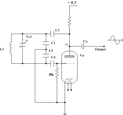
A valve radio receiver, in its simplest form, consists of a frequency-determining tuned circuit made up of an inductor and capacitor in parallel, followed by a series of valves connected together. These valves amplify the signal, perform detection (rectification),...

The ultrasonic drilling machine is essential machinery in the dairy industry for processing jewelry, primarily for natural stones, crystal agate, jade, and glass products. This machine is particularly effective for high-hardness materials, enabling both drilling and engraving. The following...

The DC arc welding machine is connected to the secondary load path of the power circuit as illustrated in the figure. This circuit is designed for use during extended downtime, approximately lasting a few minutes, and is not suitable...

An aerial voltage power supply with a continuously adjustable stabilized output ranging from 0 to 30 VDC. The circuit also incorporates an electronic current limiter that effectively controls the output current from a few milliamperes (2 mA) to a...

This project is suitable for individuals who enjoy experimenting with electronics. It presents a low risk of damaging the unit. This project involves creating a simple electronic circuit that allows users to engage in hands-on experimentation without significant risk. The...