
From Crystal Sets To 405 Line television

The valve radio receiver operates by utilizing a tuned circuit to selectively amplify specific frequencies from incoming radio signals. The tuned circuit, composed of an inductor and capacitor, resonates at a particular frequency, allowing the receiver to filter out unwanted signals and focus on the desired broadcast frequency. The valves, or vacuum tubes, serve as active components that amplify the weak signals captured by the antenna. The arrangement of valves in series enhances the overall gain and facilitates the detection of audio signals embedded within the radio frequency.
The coupling between valves can be achieved through various methods, including capacitive and inductive coupling, each having its advantages and limitations. Capacitive coupling is straightforward and allows for easy signal transfer; however, it is limited to audio frequencies due to the capacitive effects that become significant at higher frequencies. Inductive coupling, on the other hand, can handle a broader range of frequencies and is often employed in tuned circuits to maintain signal integrity.
The use of transformers in the coupling process is crucial, as they isolate the high voltage from the anode of the first valve from the grid of the subsequent valve, preventing potential damage. The transformer also enables impedance matching, which is essential for maximizing power transfer between stages. The tuned amplifier configuration enhances the selectivity and sensitivity of the receiver, ensuring that only the desired frequencies are amplified, while unwanted signals are effectively suppressed.
Variable capacitors in the tuned circuit allow for fine-tuning of the receiver to different frequencies, accommodating various radio stations. The oscillator circuit, such as the Colpitts type, plays a vital role in generating the carrier wave necessary for modulation and demodulation processes. By implementing positive feedback, the oscillator maintains a stable output frequency, ensuring that the receiver can effectively process the incoming signals.
In summary, the valve radio receiver exemplifies classic analog signal processing techniques, utilizing tuned circuits, valves, and transformers to achieve selective amplification and signal detection. This fundamental understanding of the circuit design and operation is essential for anyone working with or studying vintage radio technology.A valve radio receiver in its crudest form is a frequency determining tuned circuit, (consisting of an inductor and capacitor in parallel) followed by a series of valves coupled together. These valves act on the signal and provide high frequency amplification, detection (rectification) and low frequency amplification (audio amplification).
A louds peaker or headphones terminates the line of valves. There are several ways in which linkage can be provided between the separate valves; the basic methods will now be shown. This arrangement is shown in Figure 3a. There is a resistor (Ra) between Valve A`s anode and the H. T supply. The A. C signal on the anode of valve A is passed to valve B via capacitor C, which should be well able to withstand the H.
T supply voltage. In the event of a breakdown of this component, the grid of Valve B would be exposed to damaging H. T voltage from Valve A`s anode. Resistor Rb is to provide a path for electrons from the grid of valve B (the so-called grid leak resistor). The capacitance value of C is chosen to present low impedance to the signal to be processed. Resistance - Capacitance coupling is only suitable for use at audio frequencies (20Hz-20 KHz); above these frequencies capacitive effects in the valve reduces the gain possible from the coupled stages.
This arrangement follows the form of the capacitive-resistive coupling illustrated in diagram 3a but the resistor between the first valve`s anode and the H. T voltage is replaced by an inductor (choke). The inductor and Capacitor values will depend on the frequency that the stage is required to operate at and the impedance of Valve B`s input circuit.
This is arrangement is shown in figure 3b. It requires the use of a transformer (TR1) that is able to withstand the anode current from the first Valve A flowing through the primary without its inductance being badly effected (potentially resulting in distortion). The high tension D. C voltage on Valve A`s anode is prevented from reaching Valve B`s grid by the transformer (transformers pass only moving signal between their primary and secondary windings.
This is usually a simple valve amplifier stage, similar to the amplifier discussed in Chapter 2 but with the anode resistor being replaced with a parallel tuned circuit (see chapter 1). Often the inductive element is the primary of a coupling transformer, the secondary of the transformer may also be tuned with a capacitor.
A tuned amplifier is shown in figure 3c. It has to be understood that as far as a varying voltage is concerned, any steady D. C voltage (such as the H. T supply) is regarded as "earth". This makes the tuned amplifier easier to understand. At a specific frequency, the impedance of the tuned circuit is maximised and the varying signal at the anode will be maximised. Other (unwanted) frequencies will see the tuned circuit as low impedance and hence will not appear at the valve anode.
Variable capacitors Vc1 and Vc2 allow the frequency to which the circuit is tuned to be altered. Tuned circuits are useful at high frequencies because any "inherent" (stray) capacitance present in the valve or wiring will in form part of the capacitive element of the tuned circuit and not degrade the performance of the amplifier. An oscillator is a device that produces a varying waveform from a steady D. C. In a radio receiver they usually produce sine waves, at radio frequency (R. F), oscillators generally incorporate an LC tuned circuit. Oscillators utilise an effect known as positive feedback. Positive feedback is when a sample of an amplifier ’s output is added to the input; the effect of this is to increase the gain of the amplifier.
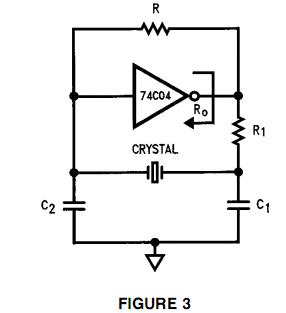
For positive feedback to occur, the feedback signal must be in phase with the applied signal. Figure 3d shows a Colpitts Oscillator circuit. An LC tuned circuit comprising Vc1, L1, C1, C2 provides a path between an amplifier output (V1 Anode) and its input 🔗 External reference
Related Circuits
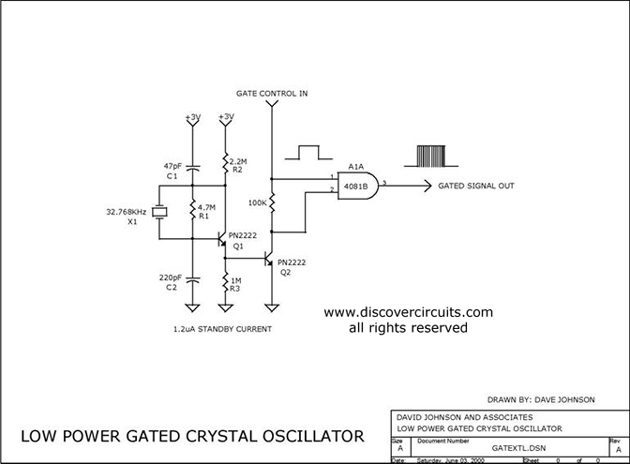
The circuit controls the output of a continuously operating 32KHz crystal oscillator, directing it to the input of a C-MOS buffer when clock pulses are required. This technique addresses the issue of a slow-starting crystal oscillator by maintaining the...
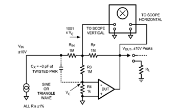
The diagram below illustrates a classic test fixture that has been utilized for an extended period to assist individuals in addressing non-linearity errors. The classic test fixture depicted in the diagram serves as a fundamental tool in electronics testing and...
A highly beneficial project involving a crystal tester circuit, also known as an xtal tester circuit, constructed with only a few components. The circuit forms an oscillator that will only oscillate if the crystal under test is functioning properly....

The finish line circuit below detects the first of three cars to cross the line and illuminates a 25 watt 120 VAC lamp indicating the winning lane. Three photo transistors are used which can be embedded into the track...
To generate a 1 MHz square wave, it is advisable to use a higher frequency crystal and divide it down for two reasons: (1) 4 MHz crystals are generally more affordable and easier to procure than 1 MHz crystals;...
High linearity analog optocouplers offer the versatility needed to address a variety of analog isolation requirements. For high voltage applications, these optocouplers can effectively transmit analog signals between high voltage and low voltage areas without introducing distortion. This article...