Magic Wand Conjuring Trick.s

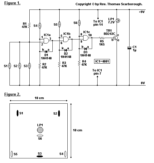
The simple conjuring trick illustrated is designed to provide enjoyment for beginners in electronics or magic, and it should take only one to two hours to construct. The trick operates as follows: a wand, equipped with a magnet at one end, must be passed in a specific 1-2-3 sequence over reed switches S4 to S6 for the bulb LP1 to illuminate. If the wand passes over reed switches S1, S2, or S3, the 1-2-3 sequence will be reset, meaning it will be canceled. Additionally, if the bulb is already lit, activating reed switches S1, S2, or S3 will turn it off. All reed switches, S1 through S6, are affixed just beneath the surface of a 10 cm² box. A general-purpose adhesive is recommended to allow for potential repositioning of the reed switches. The bulb, LP1, is centrally mounted within the box. A small PP3 9V battery can be utilized for power. The prototype box is constructed from balsa wood. The wand can be waved in various motions above the box, provided it ultimately passes in the correct 1-2-3 sequence over S4 to S6, at which point LP1 will illuminate. This design is intended to confuse onlookers, making it nearly impossible for another individual to replicate the correct motions with the same wand. The wand may also be lifted just high enough over reed switches S1 to S3 to avoid triggering them. The circuit operation is relatively straightforward. Three AND logic gates from a 4081 CMOS IC are used, with gates IC1a to IC1c configured as a standard cascaded latch circuit. S1 to S3 function as reset switches. The output at pin 10 will switch to logic high only when reed switches S4 to S6 are activated in the correct sequence. A power transistor, TR1, amplifies the output current to illuminate bulb LP1. In standby mode (when the bulb is off), the circuit consumes minimal current, thus a switch is not included in the design, though one may be added if desired. The box can be opened to easily connect or disconnect the battery.
The circuit design employs a combination of reed switches and a CMOS logic gate configuration to create an interactive magic trick that is both engaging and educational. The use of reed switches provides a non-contact method of activation, which adds an element of intrigue to the trick. The wand's magnet interacts with the reed switches, allowing for a flexible and dynamic performance. The cascading latch circuit formed by the AND gates ensures that the sequence must be followed precisely, adding to the challenge for the performer.
The choice of a PP3 9V battery as a power source is practical, providing sufficient voltage while maintaining a compact design. The use of balsa wood for the prototype not only makes the construction lightweight but also allows for easy modifications if adjustments to the reed switch placements are necessary. The design is user-friendly, enabling quick assembly and disassembly for maintenance or battery replacement.
In terms of safety, the circuit operates at a low voltage, minimizing the risk of electric shock. The low power consumption in standby mode is an efficient feature that prolongs battery life, making the circuit suitable for repeated performances without frequent battery changes. Overall, this conjuring trick not only serves as an entertaining magic act but also introduces fundamental concepts of electronics, such as logic gates, switches, and basic circuit design principles.The simple conjuring trick in Figure 1 is intended to provide some enjoyment for the beginner in electronics or conjuring, and should take only an hour or two to build. The trick works as follows: a wand (with a magnet mounted in one end) must pass in a 1-2-3 sequence over reed switches S4 to S6 before the bulb LP1 will light.
If the wand passes o ver reed switches S1, S2, or S3, the 1-2-3 sequence will be reset (that is, cancelled). Or, if the bulb is already burning, the activation of reed switches S1, S2, or S3 will extinguish it. All the reed switches - S1 to S6 - are glued just beneath the surface of a 10 cm² box (Figure 2).
A general purpose adhesive is suggested, so that the reed switches may later be moved if necessary. The bulb, LP1, is mounted in the centre of the box. A small PP3 9V battery may be used. The prototype box was built using balsa wood. The wand may be waved back and forth in various motions over the box, on condition that it finally passes in the correct 1-2-3 sequence over S4 to S6 (at which point LP1 will light). This should thoroughly confuse any onlooker and make it virtually impossible for another person to repeat the correct motions with the same wand.
The wand may also be lifted just high enough over reed switches S1 to S3 so as not to trigger them. The operation of the circuit is fairly simple. Three AND logic gates of a 4081 CMOS IC are employed, with gates IC1a to IC1c being configured as a standard cascaded latch circuit. S1 to S3 serve as reset switches. The output at pin 10 will only switch to logic high when reed switches S4 to S6 are closed in sequence.
Power transistor TR1 amplifies the output current to light bulb LP1. In "stand-by" mode (with the bulb extinguished) the circuit will use very little current. Therefore a switch is not included in the circuit (of course, one may be added). The box may be opened and the battery simply clipped on or off. 🔗 External reference


