
The Magic Eye Wink

The EM80 tube can be incorporated into amplifier projects, and it is noted that using the 8-ohm tap at the speaker jack can facilitate negative feedback while maintaining lower voltage and component ratings. There is an interest in sourcing a viewing window and trim for the head cabinet of the amplifier to protect the tube from accidental contact. Additionally, inquiries regarding the compatibility of the EM81 tube with similar connections and pinouts have been raised, with specific attention to heater connections and signal extraction points.
The circuit utilizing the Magick Eye tube, such as the EM80, involves a basic setup where the tube serves as a visual indicator for audio levels. The tube operates by illuminating a fluorescent target that reacts to the audio signal, providing a visual representation of the signal's amplitude. The required voltage levels for the tube operation must be carefully managed to prevent damage and ensure proper functionality.
To implement this circuit, the following components and connections are necessary:
- **Magick Eye Tube (EM80 or similar)**: The tube acts as the primary visual indicator. Ensure the correct pin configuration is referenced from the manufacturer's datasheet.
- **Power Supply**: A dual power supply is needed, providing a high voltage (B+) of 200 to 250 volts and a lower signal voltage of 10 to 25 volts. The lower voltage should be derived from the audio circuit output.
- **Audio Input**: The audio signal must be conditioned to match the input requirements of the tube, typically requiring a buffer stage to ensure appropriate impedance and signal level.
- **Output Connections**: Connect the audio signal to the specified pin on the tube, typically pin 3 for signal extraction in the case of the EM80. Ensure heater connections are made to the correct pins (usually pin 4 and 5) to provide the necessary filament voltage for operation.
- **Viewing Window**: Incorporate a protective glass cover over the tube to prevent accidental contact while allowing visibility of the visual effects.
This configuration allows for a functional and visually appealing addition to any tube amplifier project, enhancing both the aesthetic and operational aspects of the device. Proper attention to the electrical characteristics and safety precautions will ensure a successful implementation of the Magick Eye tube in the amplifier design.A tube commonly used as a tuning indicator in old radios. I had to try them out in my amps. So I plopped together a quick video to see the dramatic and cool visual effect. I will probably tweak some values but overall I am very happy with the visual effect. The circuit is nothing complicated. All you need is one of the many Magick Eye tubes existent out there, with many different beam patterns, that might need a slightly different pin-out connection, but all of them work in a main common way it taps in the path of the signal level of roughly 10 to 25 Volts (depends on the type of tube used), and a high DC voltage of something between 200 to 250 (B+). I used a Russian EM80/6BR5 I scored off Ebay. The EM80 tube has a U shaped fluorescent target and two rods connected to the anode, producing two angled shadows on the edge triggered by the control voltage (input signal).
Aleks It should be driven off any audio circuit. The only thing is to get the signal to a decent level & impedance accepted by the input of the magic eye tube. Hello, I`m a bit late in seeing this but thank you for posting. I will add one of these in my next build as I already have a few purchased recently. I would like to point out that I am planning on using the 8 ohm tap at the speaker jack like taken here for negative feedback when used.
Lower voltage & ratings for components instead of HT worries and with same parts count. Cheers! I have enjoyed your instructional videos and Sound Garage tales for a number of years. I have recently had an opportunity to acquire an EM80 tube and would like to incorporate it into my current amp project, much as you did with your great looking Stinger amp. I have not been able to find a source for the viewing window and trim for the head cabinet. Would it be possible for you to point me to a place where I could purchase these Do you have these available for purchase I am concerned that if the window is left as a cut-out without a glass cover, some curious individual would reach in to touch the pretty light and get somewhat of a less than pleasant surprise!
Any assistance that you could give me would be greatly appreciated. Keep up the great work! It truly is a pleasure to see someone who enjoys what they do as much as you do. Building my first tube amplifier, and I stumbled on to your page here, and I like this winking tube! I am definitely going to look into this more. I would love to put one of these tubes in my amp. Hi Gabi, just checking the coonections: I have a EM 81, will it work similar, same pinout ! are pin 4 and 5 the heater connection And which pin on an octal (6L6, EL 34 do I connect to Is that pin 3 on those Cheers, looks cool! I am not familiar with the EM81 pinout I would look up specific schematics for it. For the EM80, pin 4 & 5 are for the heaters, and indeed you would draw the signal from pin 3 on a 6L6.
🔗 External reference
Related Circuits
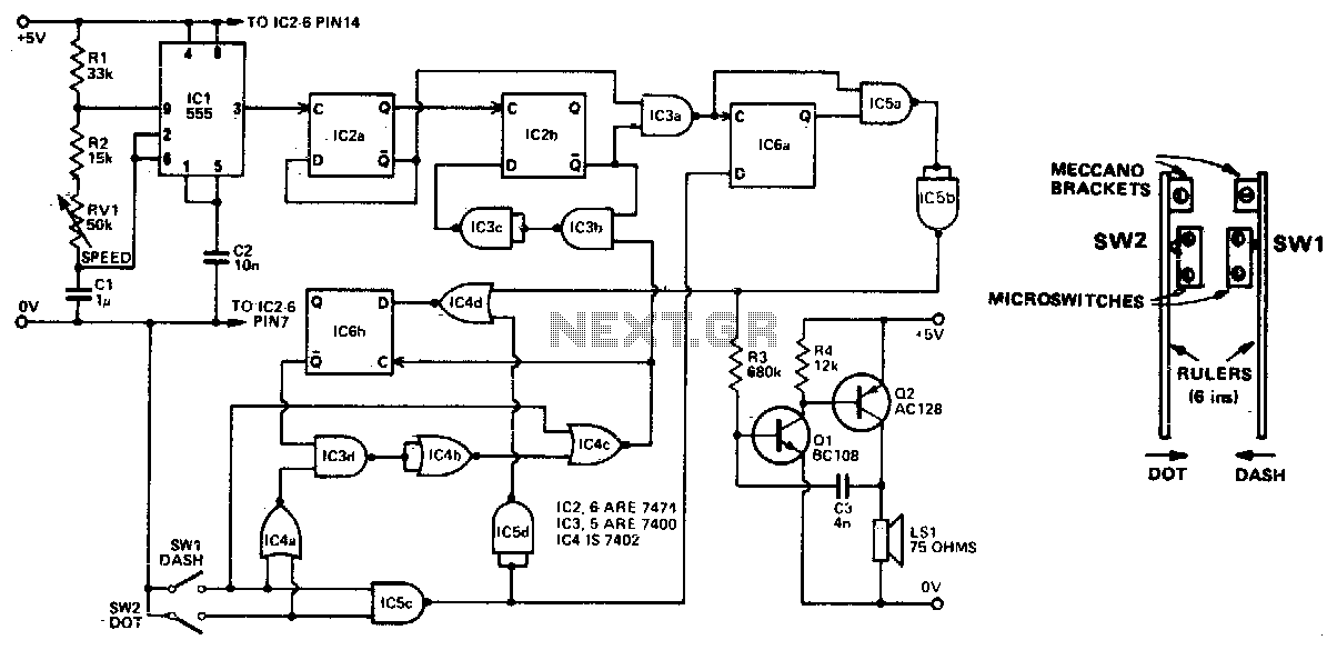
Automatically generated dits and dahs are produced over a speed range of 11 to 39 wpm. The upper limit can be raised by decreasing R2. SW1 and SW2 can be a "homebrew" paddle operated key. The described circuit is designed...
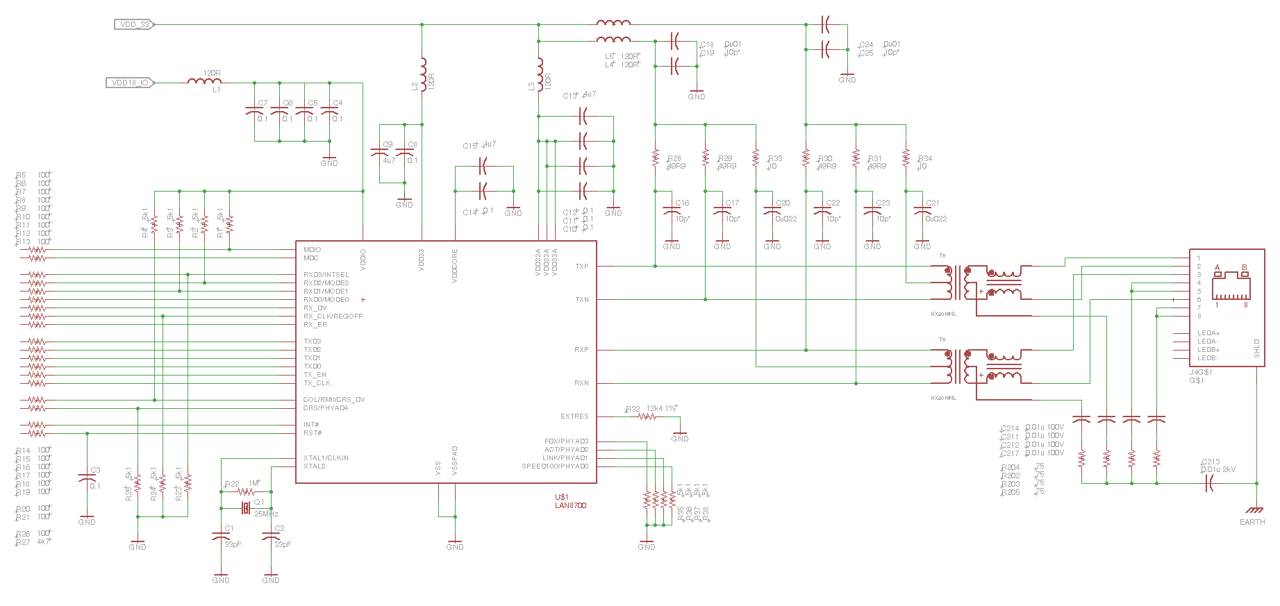
This is the eye diagram for the transmit pair. The receive pair is very similar. It is a LAN8700 PHY, and the MII interface has been effectively disabled, resulting in the PHY transmitting IDLE code sequences. It is forced...
This is not a sophisticated automatic keyer but it is lot QRP to build and to have fun operating it. When the paddle is connected to the DOT terminal, C1 starts to charge. When C1's charge reaches sufficiently high value,...
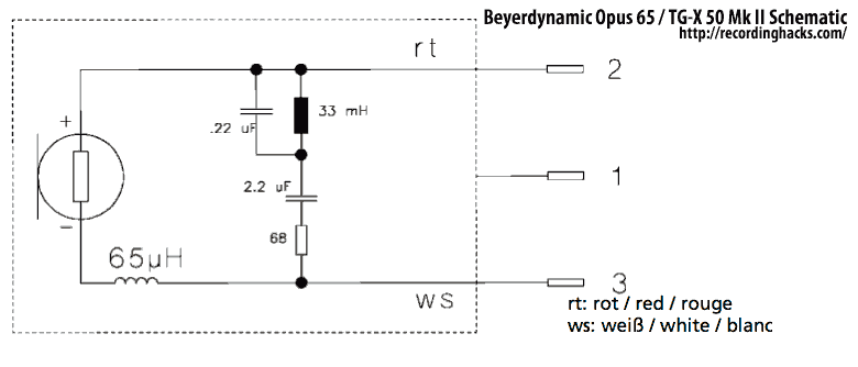
The Mk II was a second-generation version of the TG X 50. Both were dynamic microphones intended for bass instruments and kick drums. The primary difference between the two versions was the introduction of a passive EQ filter in...
When the 36 kHz infrared light emitted by the LEDs is reflected off an object, one of the receiver modules is activated. The PIC16F84 microcontroller then directs the robot to avoid the object by reversing one of the motors. The...
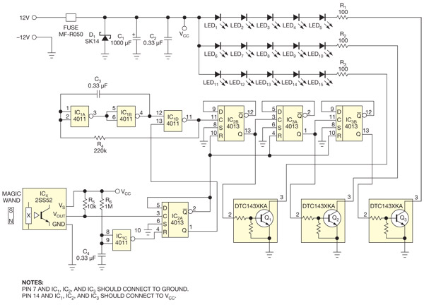
This circuit enables the activation of holiday bulbs with a wave of a magic wand. The strings of lights flash in a sequential manner. The core concept relies on a magnet. The circuit operates by utilizing a magnet as the...