
Magnetic proximity switch

The magnetic proximity switch circuit operates effectively across various fields by utilizing a magnetic reed switch (S1) that acts as the sensing element. The reed switch is sensitive to magnetic fields and closes in the presence of a magnet, allowing for the detection of proximity. The NE555 timer (IC1) functions in a monostable mode, which means it produces a single output pulse in response to the triggering event. The timing of this pulse is controlled by the resistor R2 and capacitor C2, which set the duration for how long the output remains high after the initial trigger.
Following the output pulse from IC1, the CD4013 flip-flop (IC2) is triggered, which is configured to toggle its output state. The high state at pin 1 of IC2 activates transistor Q1, which is typically used as a switch to control larger loads. When Q1 is turned on, it allows current to flow through the relay coil, thereby energizing the relay. This mechanism enables the control of various devices or equipment that are connected to the relay contacts, allowing them to be turned on or off as needed.
The circuit also includes an LED (D1) that provides a visual indication of the operation of the proximity switch. When the reed switch closes and triggers the NE555 timer, the LED illuminates, signaling that the circuit has been activated. This feature is particularly useful for troubleshooting and confirming the functionality of the circuit in practical applications.
Overall, this magnetic proximity switch circuit is a versatile solution for applications requiring non-contact detection and control, making it suitable for automation, security systems, and various industrial processes.Here is the circuit diagram of a magnetic proximity switch that finds a lot of applications in many fields. The circuit is based on a magnetic reed switch(S1) as the proximity sensor. A monostable multivibrator based on NE555 (IC1) and a toggle flip flop based on CD4013 (IC2) does the rest of the circuit.
When a magnet is reached in proximity of S1 it closes to give a negative trigger at pin 2 of IC1. The output of IC1 goes high for a time determines by R2 and C2. This clocks the IC2 wired as a toggle flip flop. The output (pin 1 ) of IC2 goes high and the transistor Q1 is biased to ON. The relay is activated and so do the equipment connected to the relay. The LED D1 glows when IC1 is triggered. 🔗 External reference
Related Circuits
The project presented is a universal QRP T/R (transmit/receive) switch designed to connect any QRP (less than 10W) receiver and CW (continuous wave) transmitter seamlessly. The design focuses on essential functionalities, making it suitable for simple transmitters and receivers...

The circuit operates using a touch electrode integrated with a base NE555, forming a double touch light switch circuit. It consists of several parts, including a simple capacitive buck converter with components Cl, C2, VDI, and VD2, which together...
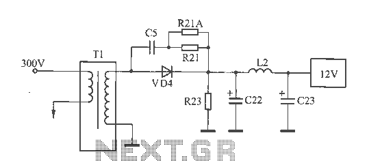
The 12V voltage instability should first be investigated by checking the output section of the switching power supply, as illustrated in the accompanying figure. The secondary winding of the transformer and the switch VD4 have been examined and found...
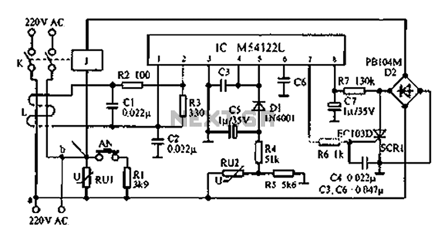
The multifunction leakage protection switch utilizes the Nissan ASIC M54122L. It is designed to serve as a multi-function leakage protection switch. In the event of leakage or electric shock, the magnetic field generated through the inductor line and neutral...
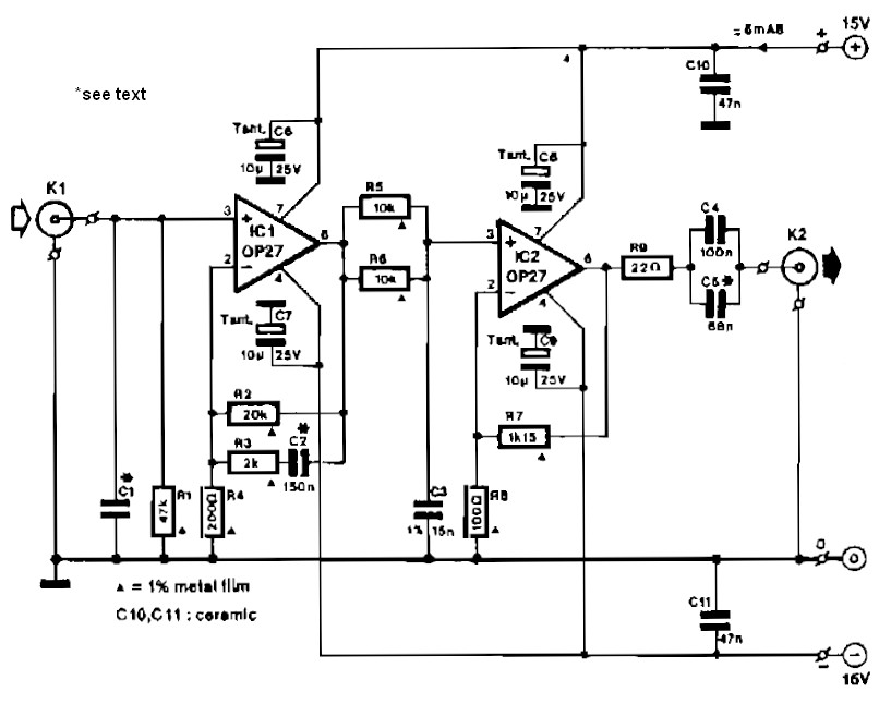
Circuit IC1 provides a gain amplification of 40 dB, which decreases to approximately 20 dB when the frequency exceeds 500 Hz. To reduce resistor noise and the load on the operational amplifier at higher frequencies, the value of resistor...
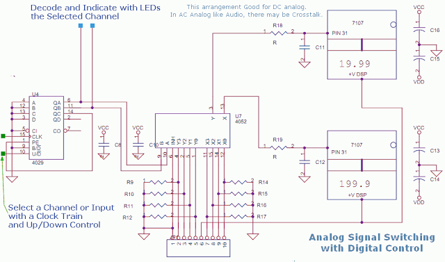
This circuit utilizes a 4052 as a DC Analog Multiplexer. The inputs to this multiplexer must originate from low-impedance output operational amplifiers (OpAmps). The resistors depicted are unnecessary once the signal conditioning OpAmps are connected. However, 100K resistors can...