
magnetic switch circuit

The magnetic switch circuit utilizes an NE555 monostable multivibrator configured to generate a single output pulse upon receiving a trigger signal from the limit switches. The circuit's design ensures that the output pulse duration can be adjusted by varying the resistor and capacitor values connected to the NE555, allowing for flexibility in response time.
The limit switches are positioned strategically to detect the presence of a magnetic field, typically generated by a magnet placed nearby. When a magnetic field is detected, the switch closes, sending a trigger signal to the NE555 multivibrator. The output pulse from the NE555 is then fed into the toggle flip-flop (CD4013), which changes its state based on the input pulse. This state change controls the relay (K1), allowing it to either engage or disengage a connected load depending on the presence of the magnetic field.
The relay (K1) serves as an interface to control higher power devices, enabling the magnetic switch circuit to operate various applications, such as security systems, automated doors, or industrial machinery. The LED indicator (D1) provides a visual confirmation of the circuit's status, illuminating when the magnetic field is detected and the relay is activated.
Overall, this magnetic switch circuit exemplifies a reliable and efficient method for detecting magnetic fields and controlling electronic devices in response to those fields.Magnetic switch is a circuit which can respond to magnetic fields that were around the sensor. The series of magnetic switches uses sensors in the form of limit switches that provide an additional metal plate that can respond to a magnet. Magnetic switch circuit is made with an NE555 monostable multivibrator and a flip-flop togle from IC CD4013.
The series of magnetic switches uses 12VDC supply voltage and the magnetic circuit is mounted indicator switch which serves to give a signal when the sensors respond to magnetic fields using the LED D1. Here is a complete range of magnetic switches. If the limit switches (sensors), active (connected) then it will get multivibrator NE555 triger signal and provides output pulses to be used to provide input signals to the flip-flop togle Relay K1 and active.
Then when the sensors (limit switches respond to the magnetic field again, the multivibrator will give togle pulse as input to the flip-flop relay K1 and non-active. 🔗 External reference
Related Circuits
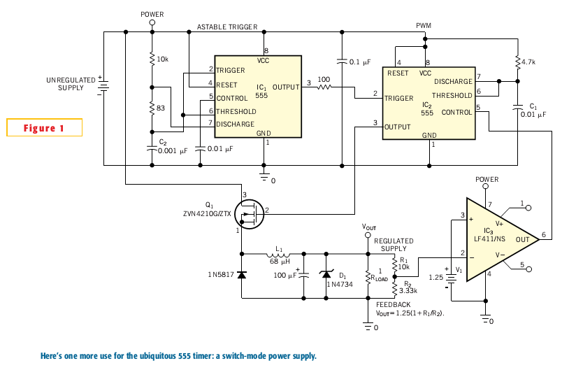
Most switch-mode power supplies utilize a PWM (pulse-width-modulated) output that is regulated through voltage feedback. A 555-timer IC can be used to generate PWM at a low cost. The circuit diagram illustrates how to convert a 555 PWM circuit...
This circuit dials a stored DTMF tone sequence from an EPROM when a control line is taken to 0 V. IC1 is a Schmitt trigger oscillator, operating at approximately 2 Hz. It clocks a 4024 binary counter. The outputs...

The video master comprises a series of converters that allocate all video sources to unused UHF channels. These channels are then combined with standard TV channels, whether terrestrial or cable, into a single cable. This single cable can subsequently...
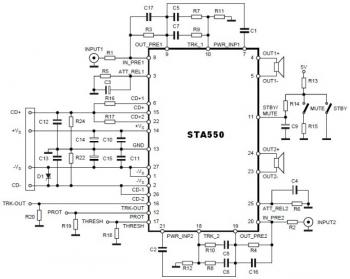
This is a stereo amplifier circuit diagram. The amplifier will produce stereo output channels with a power audio output that can reach up to 70W for each channel. The amplifier is built using the STA550 chip from STMicroelectronics. It...
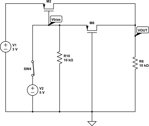
The output voltage (VOUT) is intended to be 3V when the switch is open and 5V when the switch is closed. The simulation correctly reflects the desired outcome when the switch is open; however, it does not perform as...
The FM modulator circuit, which utilizes frequency modulation, is constructed using a Motorola MC1648P oscillator. Two varactors, specifically Motorola MV-209, are employed to modulate the frequency of the oscillator. A 5000-ohm potentiometer is incorporated to bias the varactors for...