
power Switching Between Two Voltage Supplies

In the context of the circuit design, the output voltage behavior can be achieved by employing a combination of transistors and resistors to control the voltage levels effectively. When the switch is open, the circuit should be designed to pull VOUT down to 3V. This could be accomplished using a voltage divider configuration or by ensuring that the output is connected to a reference voltage of 3V through a resistor.
When the switch is closed, the circuit must allow for VOUT to rise to 5V. This could be realized by utilizing a P-channel MOSFET or an N-channel MOSFET, depending on the circuit configuration, where the gate of the MOSFET is controlled by the switch. When the switch is closed, the MOSFET should turn on, allowing the higher voltage (5V) to pass through to VOUT.
A potential issue with the observed voltage of approximately 3.6V when the switch is closed may be attributed to body diode conduction within the MOSFET or other diodes present in the circuit. This effect can cause an undesired voltage drop. To mitigate this, it is advisable to ensure that the MOSFET is properly biased and that any diode paths are accounted for in the design.
Additionally, if avoiding a common cathode diode pair is necessary, consider implementing a different configuration that can provide the required voltage levels without introducing significant forward voltage drops. A well-designed feedback mechanism could also help regulate VOUT to ensure it meets the required specifications under varying load conditions.
In summary, careful consideration of the components and their configurations within the circuit will be essential to achieve the desired voltage outputs of 3V and 5V based on the switch's state.VOUT to be 3V when the switch is open and 5V when the switch is closed. The simulation seems to give me what I want when the switch is open, but not when it`s closed. What am I doing wrong Is there a better way to do this I was avoiding a common cathode diode pair to avoid the forward voltage drop. @Gorloth. the switch exists for the purposes of simulation only. It`s meant to simulate the attaching and detatching of 5V power from the circuit. I don`t want a mechanical switch ultimately. vicatcu Apr 21 `13 at 5:40 YOu say the desired behaviour of 3v or 5v at vout, but you also say when simulated it does not work when the switch is closed, but you specify how it`s not working, if you are getting a vout that is ~3. 6v then sounds liek a body diode issue that Brian mentions in his answer below Gorloth Apr 21 `13 at 19:06
🔗 External reference
Related Circuits
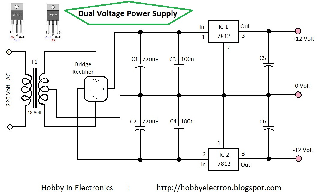
Circuit Home 7809 7812 7909 7912 Dual Voltage Hobby Electronics Hobby electronics projects RC filters REGULATOR transformer Dual Voltage Power Supply 12 Volt This is the simple circuit diagram of a Dual Voltage Power Supply. It is used for...
To construct the circuit, follow the provided schematic. If assistance is required, do not hesitate to reach out for support. If there are difficulties in identifying the components... To build the circuit effectively, it is essential to adhere closely to...
%2BCircuit%2Bdiagram%2Busing%2BCD4047%2Band%2BIRFZ44%2Bpower%2BMOSFET.png)
This simple low-power DC to AC inverter circuit converts 12V DC to either 230V or 110V AC. By making simple modifications, it is also possible to convert 6V DC to 230V AC or 110V AC. This inverter can be...
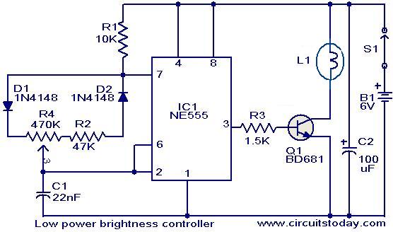
The circuit presented here is designed to control the brightness of low-power incandescent lamps. It utilizes the NE555 integrated circuit, configured as an astable multivibrator with a variable duty cycle. The output from the IC is connected to the...

RS-232C serial port lines are quite prone to be damaged by overvoltages. The damage to computer serial ports has become more and more expensive to replace because of higher integration: usually, you have to buy a new motherboard if...
An 18-year-old electrical engineering student, Chris Rieger, has been developing his levitating light bulb project, aptly named the LevLight Project, for approximately six months. Recently, he shared images and a video of the project, which gained significant attention on...