
Mains Failure Indicator

The circuit described operates as a mains failure detection system utilizing an optocoupler for isolation and a piezoelectric buzzer for audible alerts. The optocoupler's transistor serves as a switch that is activated when mains voltage is present, ensuring that the SCR remains off and the buzzer inactive. The SCR, once triggered, maintains its conducting state even when the mains voltage drops, due to its latching behavior. In this scenario, the potential difference created across the buzzer and diode D5 becomes sufficient to activate both components, providing a clear indication of power loss.
The reset mechanism is critical for restoring the circuit to its normal operational state. When the reset button is pressed, the current path through the SCR is interrupted, allowing the thyristor to stop conducting. This action effectively grounds the buzzer, silencing it until the next occurrence of mains failure. The design's reliance on a 9-V battery ensures portability and ease of use, while the low quiescent current minimizes battery drain.
Careful consideration must be given to the enclosure's insulation to prevent accidental short circuits, particularly in the region surrounding the optocoupler and associated components. The risk of damage to capacitor C2 is a significant concern; thus, it is imperative to maintain the integrity of the circuit connections. The recommendation to include a resistor across capacitor C1 serves as a safety measure, discharging the capacitor when the mains supply is disconnected, thereby preventing potential hazards during maintenance or service. Overall, this design effectively combines simplicity and functionality to provide reliable mains failure detection and alerting capabilities. When the mains voltage is present at the input terminals, the transistor in the optocoupler is on, T1 is off, and s ilicon-controlled rectifier Thl is in the conducting state. Because both terminals of the piezoelectric buzzer are then at the same potential, the buzzer is inactive. If the mains voltage drops out, transistor T1 conducts and causes one of the terminals of the buzzer to be connected to earth; the thyristor remains in the conducting state.
In this situation, a large enough potential difference is across both the buzzer and D5 to cause these elements to indicate the mains failure—both audibly and visibly. When the mains is restored, the circuit returns to its original state. A touch on the reset button then interrupts the current through the SCR so that the thyristor goes into the blocking state, and the other terminal of the buzzer is connected to ground.
The unit is powered by a 9-V battery and draws a quiescent current of 1.7-2.5 mA. It is important for the enclosure to be well-insulated. If by accident the circuit to the optocoupler and R2 is broken, electrolytic capacitor C2 might be damaged because it will be charged well above its 25-V rating. Secondly, where a plug is used for the mains connection, it is advisable to solder a 1- resistor across CI so that this capacitor does not retain its charge after the plug is removed from the mains socket.
Related Circuits
Utilizing an old moving coil instrument, it is straightforward to create a simple voltmeter that visually indicates the status of a telephone line. The circuit's high input impedance allows it to remain permanently connected to the line without drawing...

This is a simple and effective LED-based night lamp circuit that can be powered directly from a 230V mains supply. The circuit uses a total of 24 white LEDs and produces an output of approximately 15W. The resistor R1...

The three-phase voltage waveform diagram illustrates that when one phase voltage transitions from positive to negative across the zero point, the subsequent phase voltage becomes positive while the third phase remains negative. The U terminal voltage is positive when...

A TRIAC driver board designed for use in a reflow toaster oven project, which operates at mains voltages. According to IPC-2221, U.S. mains voltages necessitate a clearance of 0.4mm when coated with solder mask. Several questions arise: Is it...
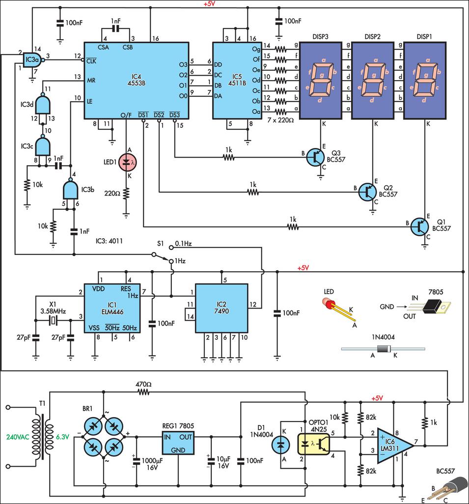
This is a simple frequency counter designed to monitor the 240VAC mains supply. It has a frequency range of 0-999Hz, making it suitable for use with 400Hz equipment as well. Standard TTL/CMOS logic is utilized for the counters and...

This battery allows the indicator to the car battery voltage monitor. The indicator has four LEDs which indicate power. The more LEDs, the higher the voltage. The last LED is a flashing LED. It comes on when the accuspaning...