
Mains Slave Switcher II

The described circuit utilizes a reed switch to control a relay via a transistor, enabling the operation of a secondary appliance based on the current drawn by a primary device. The reed switch's ability to respond to AC fluctuations ensures reliable operation, particularly in applications involving power tools that may have variable current draw. The inclusion of C3 serves to mitigate potential rapid on-off cycling of the relay, allowing for smoother operation during the zero crossings of the AC waveform. The power supply section, consisting of C1, D1, D2, and C2, is critical in converting the high-voltage AC mains into a usable low-voltage DC supply for the circuit's components.
Safety is paramount in this design due to its direct connection to mains voltage. The use of an X2-class capacitor for C1 is crucial, as it ensures the component can withstand the high voltage and potential surges present in the mains supply. The relay's coil resistance specification ensures that it operates within the limitations of the power supply, preventing overheating or failure. The enclosure design must also consider grounding and insulation to protect users from electrical hazards. Overall, this circuit represents a robust solution for controlling high-power appliances while maintaining safety and reliability.As a guide, a one-inch reed switch with 40 turns reliably switched on with the current flowing through a 150-watt lamp (approx. 625 mA) but larger reeds may require more turns. If the master appliance draws less current (which is unlikely with power tools) more turns will be required.
The reed switch is used to switch on transistor T1 which in tur n switches the relay RE1 and powers the slave appliance. Since reed switches have a low mechanical inertia, they have little difficulty in following the fluctuations of the magnetic field due to the alternating current in the coil and this means that they will switch on and off at 100 Hz. C3 is therefore fitted to slow down the transistor response and keep the relay energised during the mains zero crossings when the current drawn by the appliance falls to zero and the reed switch opens.
C1 drops the mains voltage to about 15 V (determined by zener diode D1) and this is rectified and smoothed by D2 and C2 to provide a d. c. supply for the circuit. The relay contacts should be rated to switch the intended appliance (vacuum cleaner) and the coil should have a minimum coil resistance of 400 R as the simple d.
c. supply can only provide a limited current. C1 drops virtually the full mains voltage and should therefore be a n X2-class component with a voltage rating of at least 250V a. c. The circuit is by its nature connected directly to the mains supply. Great care should therefore be taken in its construction and the circuit should be enclosed in a plastic or earthed metal box with mains sockets fitted for the master and slave appliances.
🔗 External reference
Related Circuits
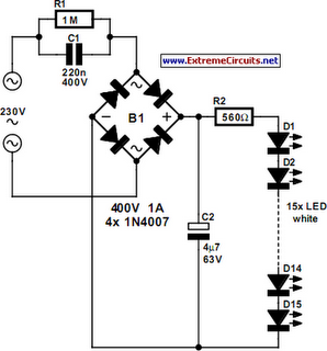
An array of white LEDs can serve as a small lamp for the living room. LED lamps are readily available, resembling standard halogen lamps, and can be installed in a standard 230-V light fixture. A capacitor is employed to...

The installation of security cameras in offices, homes, or shops has become economically viable due to the decreasing prices of security cameras. However, it is not efficient if we... The integration of security cameras into various environments such as offices,...
The circuit detects the mains current supplied to a master device and controls the on/off state of slave equipment. This functionality is particularly beneficial in environments such as hi-fi systems or home computers, where multiple peripheral devices can be...
This circuit alerts users with an alarm whenever the AC mains supply fails. It also provides a backup light to assist in locating a torch or generator key in the dark. The circuit is powered by a 9V PP3/6F22...
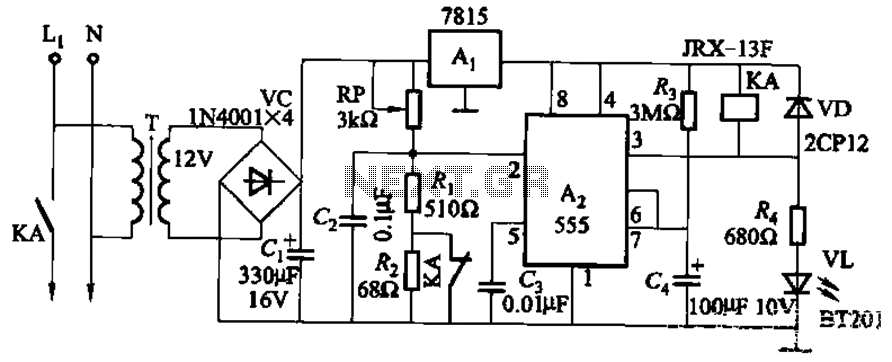
This circuit is applicable in refrigerators and other protective devices. It employs a 7815 three-terminal voltage regulator integrated circuit and an NE555 timer IC configured as a one-shot circuit for delay control. When the voltage drops below 180V, relay...
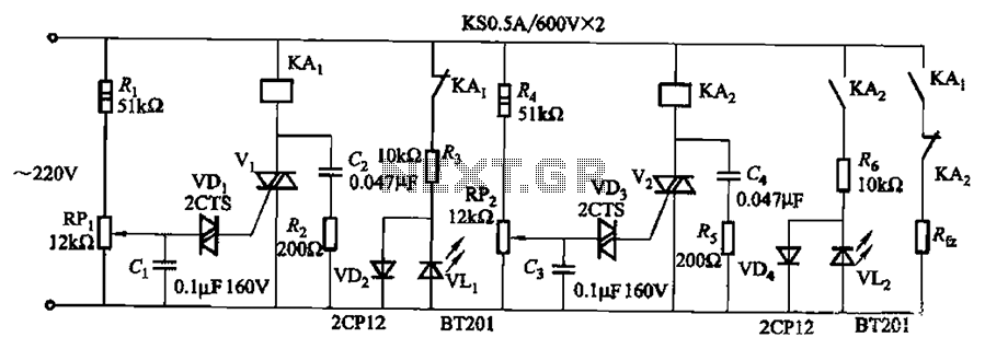
Bidirectional thyristor control. By adjusting potentiometers RPi and RPz, the lower and upper limit values can be changed. LEDs VLi and VL2 serve as indicators for low pressure and high pressure, respectively. The circuit utilizes a bidirectional thyristor to control...