
Mains undervoltage overvoltage protection circuit of five

The circuit utilizes a bidirectional thyristor to control the power delivered to a load based on pressure measurements. The configuration includes two adjustable potentiometers, RPi and RPz, which set the thresholds for low and high pressure. The adjustment of these potentiometers allows for fine-tuning of the circuit's response to varying pressure levels.
When the pressure falls below the threshold set by RPi, LED VLi is activated, indicating low pressure conditions. Conversely, when the pressure exceeds the threshold established by RPz, LED VL2 lights up, signaling high pressure. This visual feedback is crucial for monitoring system performance and ensuring safety by alerting operators to potential issues.
The bidirectional thyristor is selected for its ability to control AC loads effectively, allowing for smooth operation without mechanical wear. The circuit may also include additional components such as resistors for current limiting, capacitors for filtering, and potentially a microcontroller for more complex logic and control features.
In summary, this circuit design provides a robust solution for pressure monitoring and control, integrating visual indicators and adjustable settings to enhance its functionality and user experience. Bidirectional thyristor control. Adjust potentiometer RPi and RPz, you can change the lower and upper limit values. LEDs VLi and VL2 are less pressure and overpressure indicato r.
Related Circuits
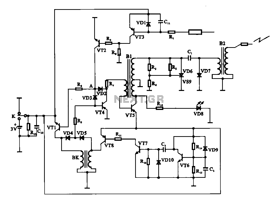
An electronic ignition circuit for a water heater is presented. When the faucet is opened, the switch activates a 3V battery. As capacitor C2 requires time to charge, transistor VT6 remains off. Meanwhile, capacitor C3 charges, allowing transistors VT7...
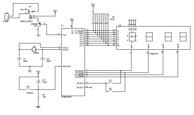
The circuit diagram above illustrates the Clock Controller V1.1. Pins P3.0 to P3.3 are connected to the base of a 4-PNP transistor, specifically the 2N2907, which is used to sink current. The Clock Controller V1.1 circuit is designed to manage...
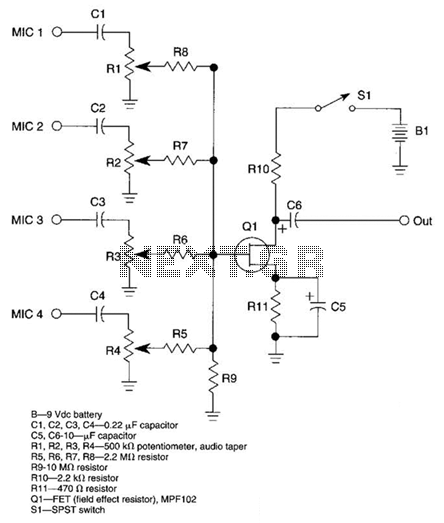
A JFET transistor is utilized as a high-to-low impedance converter and signal mixer. The input impedance is approximately 50.0 kΩ, which can be increased by adjusting resistors R5 to R8 up to 10 MΩ. The output impedance is around...
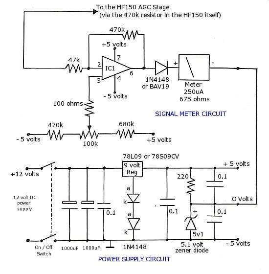
The operational amplifier (op-amp) used in the signal meter circuit is the TL061. The LF351 can also be used interchangeably, as it has the same pin layout. For those using a TL062 or similar models, the differing pin configurations...
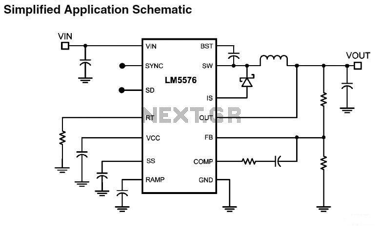
LM5576MHX absolute maximum ratings: (1) VIN to GND: 76V; (2) BST to GND: 90V; (3) PRE to GND: 76V; (4) SW to GND (Steady State): -1.5V; (5) BST to VCC: 76V; (6) SD, VCC to GND: 14V; (7) BST...
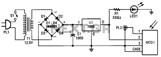
A schematic diagram for the remote analyzer is presented. The circuit is powered by a simple 5-V supply, which includes components such as PL1, SI, Tl, a bridge rectifier formed by diodes D1 through D4, capacitor CI, and a...