
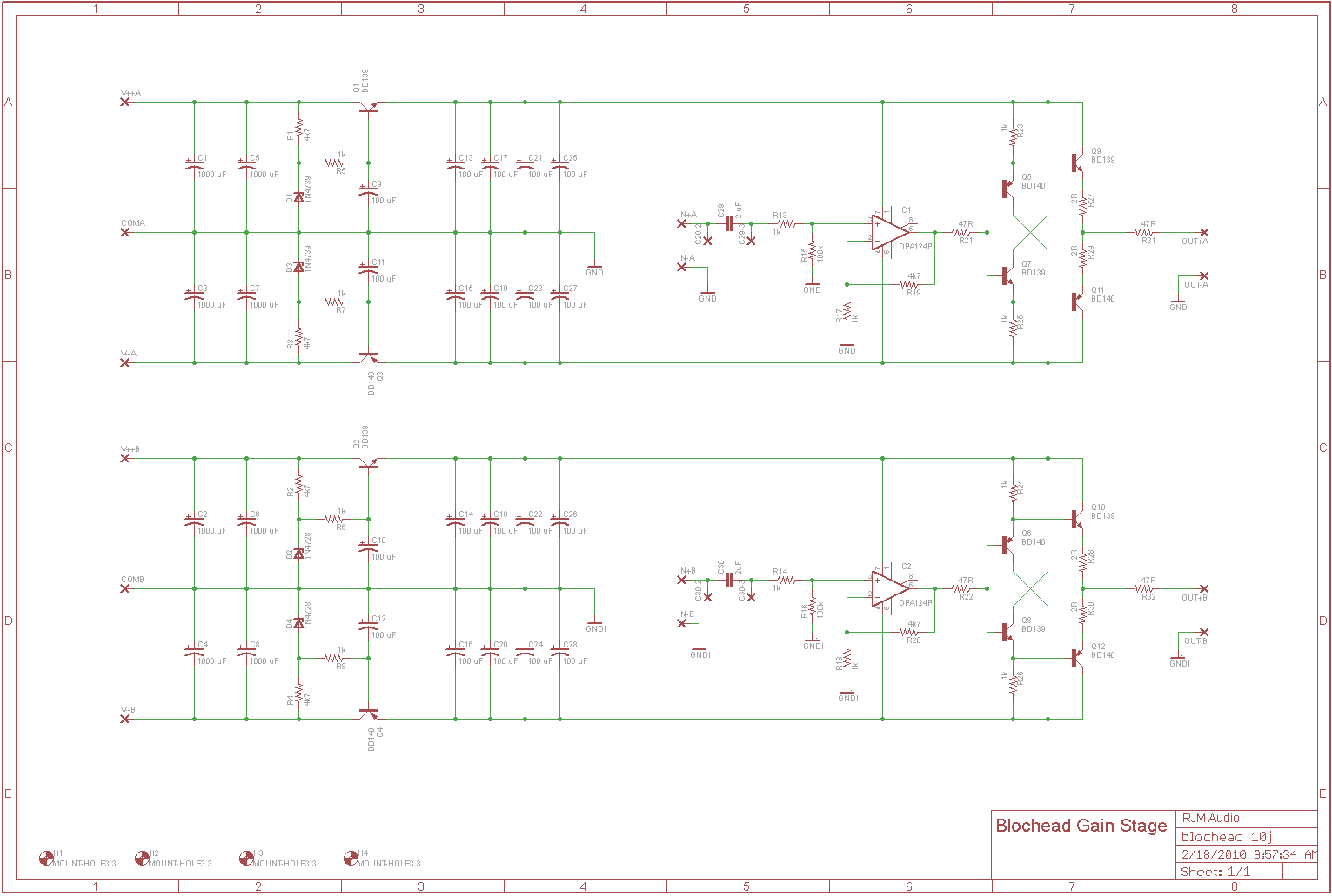
Making a BD139 voltage follower buffer

The described circuit involves a transistor amplifier configuration with an operational amplifier and a rail splitter for improved performance. The placement of R4 at the emitter of the transistor is crucial for ensuring proper biasing and stability. In this configuration, the operational amplifier drives the transistor, which amplifies the signal for headphone output. The use of a TLE2426 rail splitter allows for a dual supply voltage from a single power source, which is beneficial for audio applications as it creates a virtual ground for the amplifier's signal processing.
The modifications made to the amplifier, including the removal of input capacitors and the upgrade of components such as capacitors and rectifier diodes, suggest an effort to improve audio fidelity and performance. The absence of input capacitors may have contributed to the increase in noise levels when the gain was adjusted, indicating that careful consideration of component choices and configurations is necessary to maintain sound quality.
The buzzing noise observed when the amplifier was configured to a higher gain indicates potential issues with electromagnetic interference (EMI) or radio frequency interference (RFI). The close proximity of the transformer to the amplifier circuit can exacerbate these issues, as transformers can emit magnetic fields that induce noise in nearby circuits. The recommendation to change the orientation of the transformer is a practical approach to mitigate this interference, as it can alter the magnetic coupling between the transformer and the amplifier.
In summary, the configuration and component selection in the described amplifier circuit are critical for achieving desired audio performance. The interplay between gain settings, component placement, and external interference sources must be carefully managed to optimize the circuit's functionality and sound quality.Schematic shows R4 at the emmiter of the transistor, as amb and majkel have suggested it should be between the opamp and transistor, this is also the correct configuration in the canamp. The amp i managed to get a look at has been modified and has had the input capacitors removed, with no measurable problems, as well as having a regulated
PSU and upgraded caps and rectifer diodes. Yes. Better yet, do it M ³/Mini ³/PPA/Pimeta style. Use a TLE2426 as rail splitter for the nil-current signal ground, and use your 3rd channel to drive the output ground return from the headphone. The ground channel will source/sink the combined return current from the left and right channels, and if such signal is in-phase mono, then it would indeed be double.
But the BD139 output stage has plenty of current capability so it doesn`t really matter. Now I`m not sure what this actually did and it does sound great, but the gain is too low and I wanted to raise it. When I "fixed" the amp by making it exactly by the schematic, I got a very nasty buzzing noise in the headphones.
Still no offset, just this irritating buzzing noise. Not really a hum, a definite buzz. The thing that I`m curious about is that there was absolutely no noise when it was configured as a unity gain buffer and there is quite a bit of a buzz now. Any ideas how that happened There is a difference of almost 16dB between unity gain and gain of 6. Any amount of inherent noise, as well as interference (most likely from the transformer, but you could also have other sources of RFI and EMI) are amplified by the gain of the amp.
4 inches between the transformer and the amp is not a lot of distance especially if the transformer is sizable or if it`s an EI-core unit. You can try turning the transformer so that the mounting orientation is changed, to see if it makes any difference.
🔗 External reference
Related Circuits
The circuit is intended to operate with a 100k volume potentiometer and can function as either a line stage or a headphone amplifier. It features a standard non-inverting gain stage with a gain of 15 dB, followed by a...
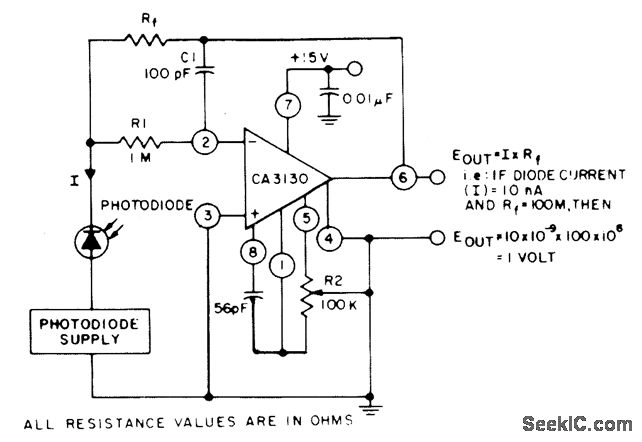
The circuit employs three CA3130 BiMOS operational amplifiers in an application that is sensitive to sub-picoampere input currents. It generates a ground-referenced output voltage that is proportional to the input current flowing through the photodiode. The described circuit utilizes three...
The hobby circuit described can be connected to a 3V battery to provide a warning when the battery is nearing its end of life. It will flash an LED when the battery voltage drops to approximately 2.4 volts. The...
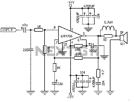
The NS LM4766, launched by a US company, is a two-channel power amplifier integrated circuit. Each channel can output an average power of 40W at an 8-ohm load, with distortion levels lower than 0.1%. It is part of National...
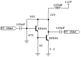
A 3KHz-50MHz signal generator is available, and there is a requirement to amplify its 2.3mW output to +7dBm. The need is for a broadband amplifier capable of achieving this amplification. To amplify the output of a signal generator from 2.3mW...
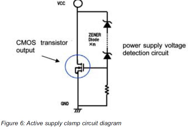
This article presents a high reliability 1200V High Voltage Integrated Circuit (1200V HVIC) for half bridge driver applications, aimed at reducing the IC's supply current by approximately 50%. The 1200V High Voltage Integrated Circuit (HVIC) is designed specifically for half-bridge...