
Manual Headlight/Spotlight Control For Autos Circuit

The circuit utilizes a NE555 timer in monostable mode, which is triggered by the pressing of the START pushbutton. When the button is pressed, the NE555 generates a high output for a time period defined by the resistor R1 and capacitor C1. The time duration can be calculated using the formula T = 1.1 * R1 * C1, where T is the time in seconds. In this case, R1 and C1 are chosen to provide a 1-minute delay.
The output from the NE555 timer is connected to a relay or a transistor switch that controls the power to the headlights or spotlights. The selection of headlights or spotlights can be achieved through additional circuitry, such as a toggle switch that determines which lights are activated when the START button is pressed.
Once the predetermined time elapses, the NE555 timer output goes low, deactivating the relay or transistor and turning off the lights. This feature ensures that the lights do not remain on indefinitely, thereby conserving battery power and preventing potential overheating or damage to the lighting elements.
For optimal performance, R1 and C1 should be selected based on the desired timing and the characteristics of the lights being controlled. It is also advisable to include a diode across the relay coil to prevent back EMF from damaging the NE555 timer when the relay is turned off. Additionally, proper power supply decoupling capacitors should be placed near the NE555 to ensure stable operation.
This circuit is suitable for automotive applications where temporary lighting is required, providing convenience and safety for users. Pressing the START pushbutton turns on either the headlights or spotlights for a predetermined time. After 1 minute (Rl and CI determine this), the lights will shut off as the NE555 completes its cycle.
Related Circuits
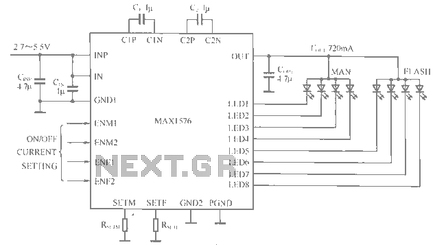
The MAX1516 charge pump drives up to 8 white LEDs with constant current regulation to achieve uniform light intensity, capable of delivering up to 30mA per LED for backlighting. The flash group LEDs (LED5 to LED8) are individually controlled,...
The water tank overflow liquid level sensor alarm circuit is a straightforward electronics project suitable for school students. Previous discussions have covered numeric water level indicators and water level controller circuits, which are more complex and intended for engineering...
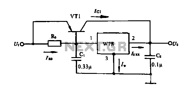
Extend the current application circuit. The maximum output current of the integrated three-terminal device in production is 1.5A. If the output current exceeds 1.5A, an external power transistor can be utilized to increase the output current, as illustrated in...
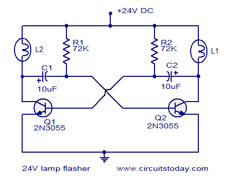
The circuit operates on 24V DC and is designed to alternately flash two 24V bulbs. It functions as an astable multivibrator with a frequency of 1Hz and a duty cycle of 50%. The lamps to be flashed are connected...
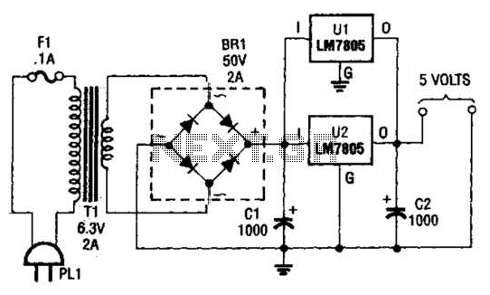
This DC supply is excellent for operating battery-powered antique radios, as it is designed to prevent damage to the tube filaments. The circuit is useful for powering the filaments of 00-A, 01-A, 112A, and 71A tubes, which require 5V...
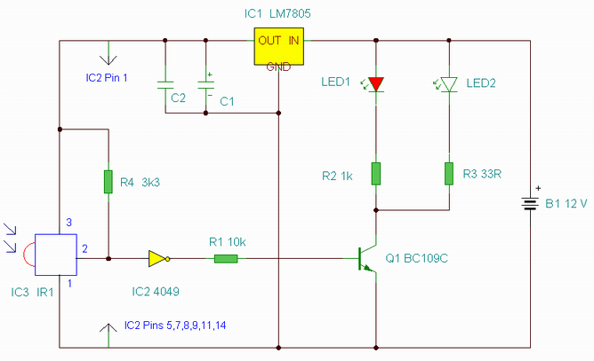
This is an enhanced infrared (IR) remote control extender circuit. It features high noise immunity, resistance to ambient and reflected light, and an increased operational range. The improved IR remote control extender circuit is designed to extend the range of...