
Mark Harrington 3 in 1 Door Bell

The Mark Harrington 3 in 1 Door Bell circuit is designed to provide multiple functionalities in a single device, integrating a power supply and various operational components. The power supply section is crucial for ensuring that the entire circuit operates reliably and efficiently.
TR1 refers to a transformer that steps down the voltage from the mains supply to a lower level suitable for the doorbell circuit. This transformer is typically chosen based on the required output voltage and current ratings to ensure it can handle the load without overheating.
Q3 is likely a transistor that functions as a switch or amplifier within the circuit. Its role may involve controlling the flow of current to other components, such as the chime or LED indicators, depending on the doorbell's state (e.g., pressed or idle).
D13 and D9 are diodes that serve to rectify the AC voltage output from the transformer into a DC voltage, ensuring that the circuit receives a stable and usable power supply. The choice of diodes is critical, as they must be rated for the appropriate current and voltage levels to prevent failure.
Q1 could be another transistor or a part of a relay circuit that activates the doorbell chime or other features when the button is pressed. This component may also include additional elements, such as resistors or capacitors, to filter noise and stabilize the operation.
In summary, the Mark Harrington 3 in 1 Door Bell circuit is a carefully designed system that integrates a power supply and control components to deliver a reliable doorbell solution with multiple functionalities. Each component plays a specific role in the overall operation, contributing to the efficiency and effectiveness of the device.Mark Harrington 3 in 1 Door Bell. The circuit comprises the power supply which is formed by TR1, Q3 , D13 , Q1 , D9.. 🔗 External reference
Related Circuits
To put the relay in tension the 4 buttons S1 S4 must be pressed. If anyone of the 4 buttons S5 S8 are pushed the relay doesn't tension (doesn't receive supply voltage). The supply voltage must be equal to...
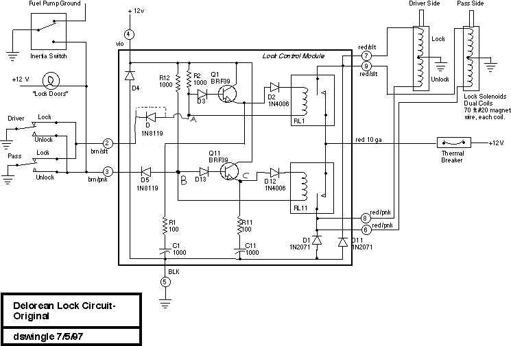
This document discusses the enhancement of a lock control module, providing instructions and photographs for upgrading the module to minimize its standby current consumption, thereby extending battery life. It is assumed that the user possesses a basic level of...
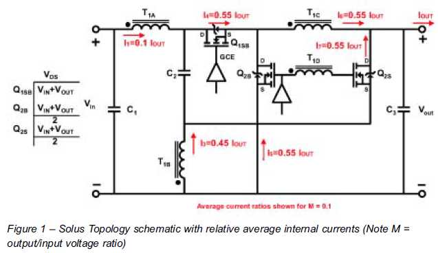
The ability to reduce power losses is crucial. This document describes a new ultra-high-performance topology that is expected to serve as the foundation for next-generation DC-DC power supplies in high-demand applications. The proposed ultra-high-performance topology aims to significantly enhance the...
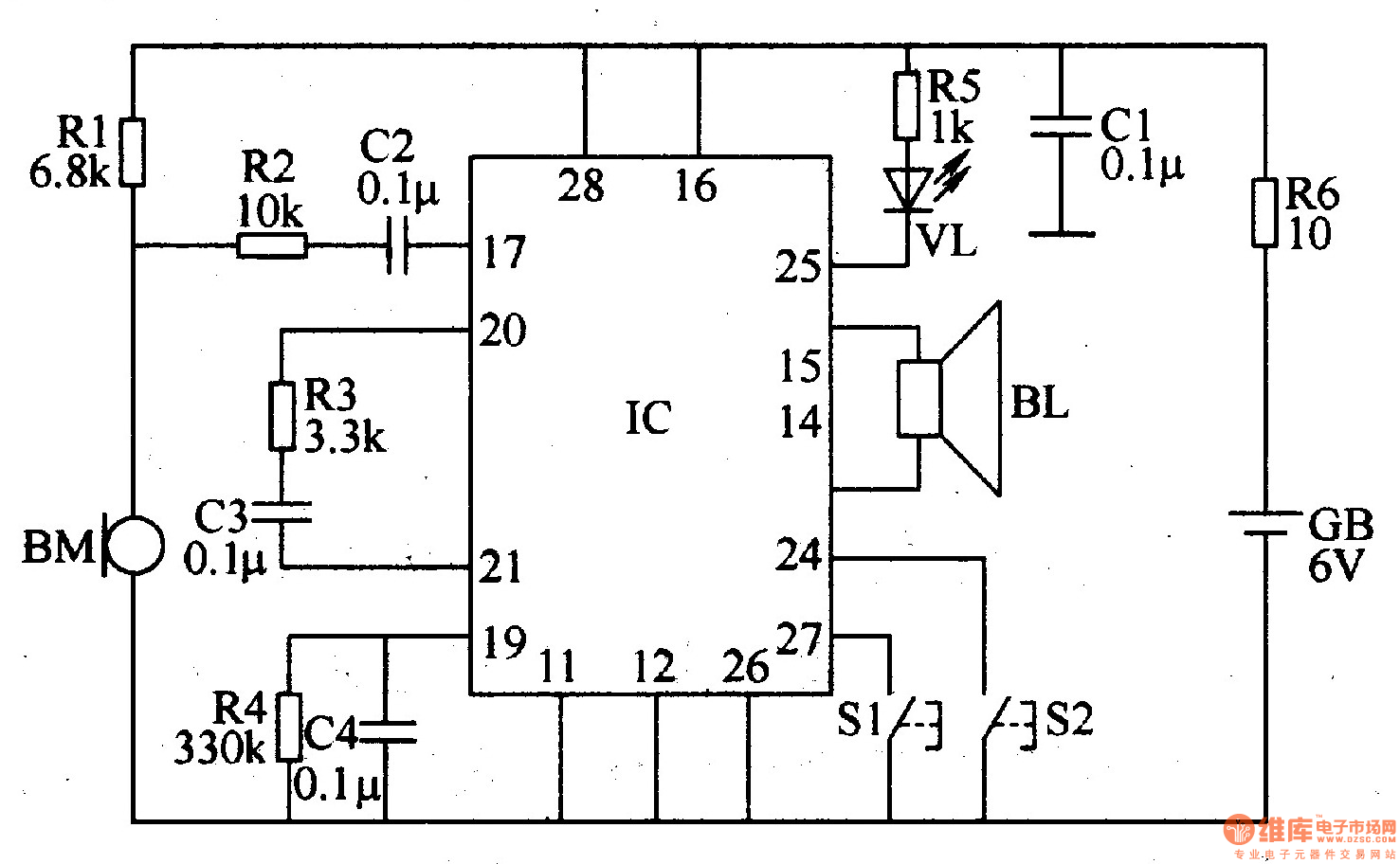
The recordable electronic doorbell consists of a recording and playback integrated circuit (IC), resistors R1-R6, capacitors C1-C4, a microphone (BM), a speaker (BL), control buttons S1 and S2, a battery (GB), and an LED (VL). Resistors R1-R5 should be...
Instructions for wiring and installing a doorbell in your home. The installation of a doorbell involves several key steps to ensure proper functionality and safety. The process typically begins with selecting the appropriate doorbell type, which can be either wired...
Understanding the pins of an integrated circuit (IC) is crucial for circuit construction. Pin 1 (GND) is connected to ground, representing a low voltage level (0 V). Pin 2 (TRIG) is used to trigger the operation of the circuit....