
Recordable electronic doorbell
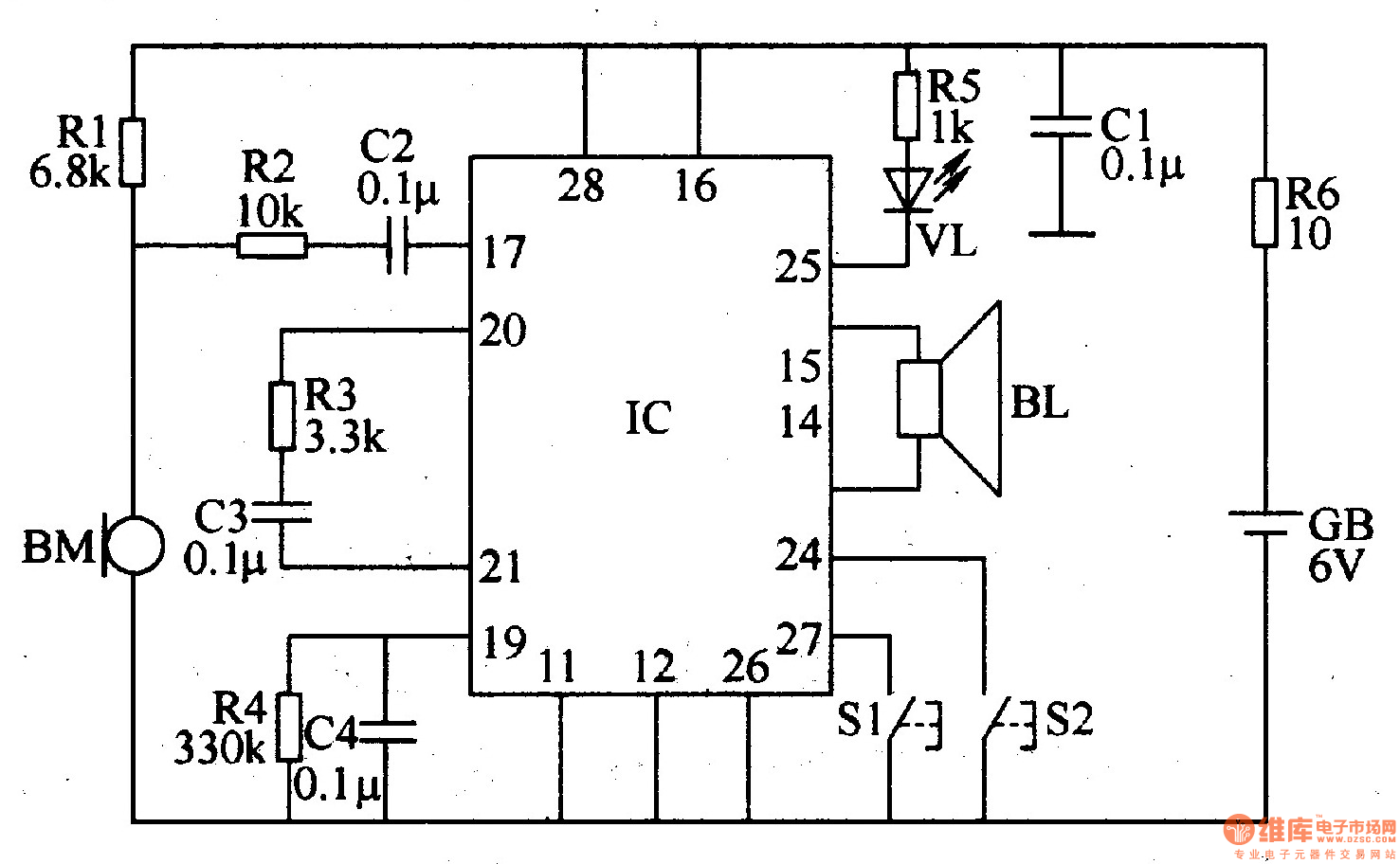
The recordable electronic doorbell functions as an interactive alert system, allowing users to record personalized messages for visitors. The core component of this circuit is the recording and playback integrated circuit (IC), which handles the storage and retrieval of audio messages. The microphone (BM) captures the audio input, while the speaker (BL) outputs the recorded messages.
Resistors R1 to R5 are utilized in the circuit to set appropriate biasing levels and to limit current flow, ensuring the safe operation of the IC and other components. The choice of 1/4W metal film or carbon film resistors for R1-R5 is critical for maintaining stability and reducing noise in the audio signal. R6, selected as a 1W metal film resistor, may be used in a part of the circuit that requires higher power handling, such as in the output stage driving the speaker.
Capacitors C1 to C4 play a vital role in filtering and decoupling, ensuring that the power supply to the IC remains stable and free from noise. They may also be involved in timing applications within the circuit, depending on their values and configuration.
Control buttons S1 and S2 provide user interaction, allowing for the recording and playback of messages. These buttons are typically connected to the IC in such a way that pressing S1 initiates recording, while pressing S2 triggers playback.
The battery (GB) supplies the necessary power for the entire circuit. It is essential to select a battery with adequate voltage and capacity to ensure the longevity and reliability of the doorbell.
Finally, the LED (VL) serves as a visual indicator, signaling when the doorbell is active or when a message has been successfully recorded or played back. Proper placement of the LED within the circuit is essential for clear visibility to the user.
Overall, the design of the recordable electronic doorbell integrates various electronic components to create a functional and user-friendly device, enhancing the traditional doorbell experience with personalized audio messages.The recordable electronic doorbell is composed of the recording and playback integrated circuit IC, resistors Rl-R6, capacitors Cl-C4, microphone BM, speaker BL, control buttons Sl, S2, battery GB and LED VL, and it is shown in Figure 3-123. Rl-RS select 1/4W metal film resistors or carbon film resistors; R6 select the lW metal film resistor.
Cl-C4 select mo.. 🔗 External reference
Related Circuits
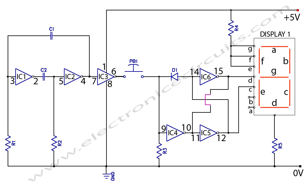
Electronic Coin Toss Circuit Diagram. This is an electronic coin toss circuit using one CD4049 IC (Hex inverting buffer and TTL driver). The electronic coin toss circuit utilizes the CD4049 integrated circuit, which serves as a hex inverting buffer...
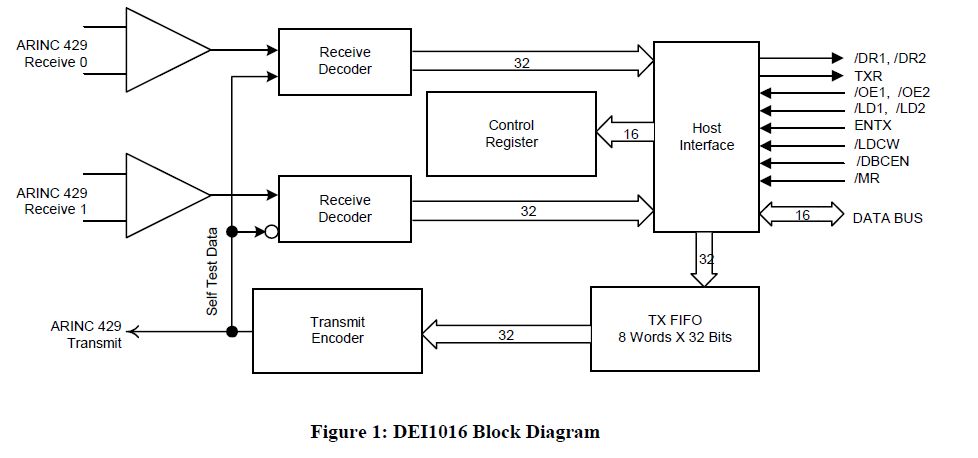
This document outlines the process of interfacing an Arduino with an ARINC 429 transceiver, illustrating the general methodology for connecting an Arduino to electronic circuits that can be applied to individual designs. The ARINC 429 bus is the predominant...
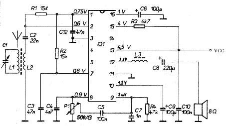
This AM radio receiver circuit utilizes the TDA1083 radio IC, which is suitable for constructing a simple medium frequency (MF) band radio. The schematic operates within a frequency range of 300 kHz to 3 MHz. The circuit is straightforward...
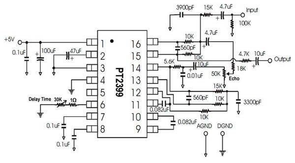
A single-chip circuit for echo and delay. If a microphone mixer circuit can be modified, this circuit can be easily used with a microphone. The PT2399 is an echo audio processor integrated circuit (IC) that utilizes CMOS technology and...
This circuit is a simple and cost-effective design that utilizes an operational amplifier IC 741 (IC1) alongside a push-pull amplifier made with transistors for signal amplification. The project name indicates its intended application, which includes level control in hydroponic...
Individuals who frequently utilize battery-operated devices or require a negative voltage from a single positive source will find the following converter beneficial. This circuit can convert a 9 V positive battery voltage to a negative voltage using the well-known...
Warning: include(partials/cookie-banner.php): Failed to open stream: Permission denied in /var/www/html/nextgr/view-circuit.php on line 713
Warning: include(): Failed opening 'partials/cookie-banner.php' for inclusion (include_path='.:/usr/share/php') in /var/www/html/nextgr/view-circuit.php on line 713