
MAX8903A charger circuit diagram

The charger integrated circuit (IC) is designed to efficiently manage power input from two sources: a DC input and a USB input. The DC input is capable of handling voltages between 4.15V and 16V, making it suitable for various applications where a stable and higher voltage is required. The inclusion of a protection feature that allows for a maximum input voltage of 20V ensures that the circuit remains safe from overvoltage conditions, which could potentially damage the IC or connected components.
On the other hand, the USB input is optimized for lower voltage applications, operating within a range of 4.1V to 6.3V. This range is typical for USB-powered devices, allowing for compatibility with standard USB power supplies. The protection limit of 8V serves as a safeguard, preventing damage from voltage spikes or surges that may occur during operation.
Incorporating both input options allows for versatility in design, making this charger IC suitable for a wide range of electronic devices. The ability to switch between DC and USB power sources enhances the usability of the device, providing flexibility in power management.
Additional design considerations may include the implementation of filtering capacitors at the input to smooth out voltage fluctuations, as well as thermal management solutions to dissipate heat generated during operation. Proper layout techniques, including trace width calculations and grounding strategies, will also contribute to the overall performance and reliability of the circuit.The DC input for this charger ic operates from 4. 15V to 16V with up to 20V protection, while the USB input has a range of 4. 1V to 6. 3V with up to 8V protection. 🔗 External reference
Related Circuits
A milliamp meter can function as a voltmeter by incorporating a series resistance. The required resistance is calculated by dividing the full-scale voltage reading by the full-scale current of the meter movement. For instance, using a 1 milliamp meter...
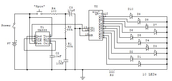
This electronic circuit is a simplified version of an electronic roulette game, utilizing the 4017 integrated circuit (IC), which functions as a 10-stage decade counter/divider. It is driven by a versatile 555 IC configured as a voltage-controlled oscillator (VCO)....
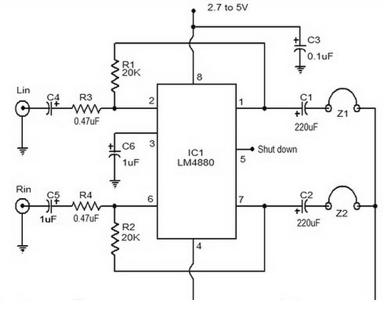
The LM4880 is a dual audio HiFi amplifier integrated circuit from National Semiconductor. This headphone amplifier circuit is specifically designed to produce high-quality audio output with a minimal number of components. The LM4880 integrated circuit is capable of delivering...
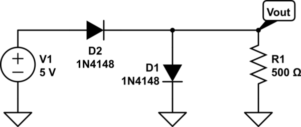
The two diodes will fail. It is advisable to include series resistors for them. If the simulation is successful, the current through the diodes will be excessive. Both diodes do not necessarily need to fail; one may become a...
A 6V to 12V DC converter circuit is designed to convert a lower voltage of approximately 6 volts to a higher voltage of 12 volts, albeit with a reduced current rating. This inverter circuit can deliver up to 800mA...
The circuit consists of two differential amplifier transistors configured with a voltage dividing type bias circuit, measuring the resistance of four arms in a bridge configuration. The product includes a platinum resistance sensor, which exhibits an increase in resistance...