
MCS08DZ60 Evaluation Board

- 60K of Flash memory;
The other parts of the schematic are not so special, we can find:
- The power supply, built around a DC/DC converter (IC1; a classical linear voltage regulator like 7805 can also be used without any modification of the PCB);
- A LED to indicate that the board is supplied (LED1);
- A switch connected on the RESET pin of the microcontroller (S1);
- The crystal (Q1). Note that the crystal is connected to the microcontroller through jumpers: the device can work with an internal clock and in this case, the pins are available as classical GPIOs.
- Finally, there are some decoupling capacitors for all integrated circuits.
The power of the board will be applied on K1. Any power supplied can be used if it provided between 8 to 12 Volts AC or DC. K2 will be used to connect the programming cable, and K3 gives access to all the pins of the microcontroller. K3 is built with two arrays of connectors to plug a module on the evaluation board (see photo #1).
- 4Ko of RAM;
- 2Ko of EEPROM;
- Integrated CAN bus controller;
- Integrated SCI controller with LIN capability;
- Integrated I2C controller;
- Integrated SPI controller;
- Analog inputs, with a resolution of 12bits;
- Timers which can generate PWM signals;
To program the microcontroller, a programming cable for Freescale HCS08 devices is required, along with CodeWarrior for Microcontrollers available from the Freescale website. This small evaluation board is easy to build and will enable numerous experimentations. Two boards can be made to create a small network through the CAN interface. This board is also suitable for developing applications around I²C, SPI, SCI, etc. The peripherals available on the 8-bit devices from Freescale are the same as those on the 16 and 32-bit devices, such as the Coldfire, making this board an excellent starting point for programming and learning with Freescale devices.
The evaluation board features a comprehensive layout designed for educational and prototyping purposes, emphasizing CAN communication. The CAN transceiver (IC4) enables the board to interface with other CAN devices, facilitating the development of automotive applications and networked systems. The RS232 transceiver provides a reliable means of connecting to computers for debugging and programming, enhancing the versatility of the board.
The microcontroller (68HCS08DZ60) is equipped with a robust set of features, including ample memory resources (60K Flash, 4K RAM, and 2K EEPROM) and various integrated communication protocols such as CAN, SCI, I²C, and SPI. These capabilities allow for a wide range of applications, from simple GPIO manipulation to more complex tasks involving data communication and control.
The power supply section of the board is designed to accommodate a variety of input voltages (8 to 12 Volts AC or DC), ensuring compatibility with different power sources. The use of a DC/DC converter (IC1) provides efficient voltage regulation, while the option to use a linear voltage regulator like the 7805 offers flexibility in power management.
Additional features, such as the onboard LED (LED1) for power indication, the reset switch (S1), and the crystal oscillator (Q1) with jumper options for clock configuration, contribute to the overall functionality and ease of use of the board. Decoupling capacitors are strategically placed to ensure stable operation of the integrated circuits, minimizing noise and potential interference.
The board's design facilitates easy access to the microcontroller's pins through K3, allowing for the connection of additional modules or components. This modular approach supports various experimentation scenarios, making the board a valuable tool for learning and development in embedded systems and microcontroller applications.The board has been initially developed to learn with CAN, so a CAN transceiver is available (IC4). The CAN transceiver comes from Maxim, but some other manufacturers provide some compatible CAN transceivers which can be used. An RS232 transceiver is also mounted on the board to get an RS232 interface, to connect the board to a computer.
It could be used for debug purpose for example. Both transceivers are connected to the microcontroller throw jumpers, so it is possible to disconnect the transceivers and use the pin of the microcontroller as classical GPIOs. The microcontroller used is the 68HCS08DZ60, from Freescale, and coming with an LQFP32 package. It is initially a microcontroller designed for automotive applications. It has some very interesting features: - 60K of Flash memory; The other parts of the schematic are not so special, we can found: - The power supply, build around a DC/DC converter (IC1 ; a classical linear voltage regulator like 7805 can also be used without any modification of the PCB); - A LED to indicate that the board is supplied (LED1); - A switch connected on the RESET pin of the microcontroller (S1); - The crystal (Q1). Note that the crystal is connected to the microcontroller throw jumpers: the device can work with an internal clock and in this case, the pins are available as classical GPIOs.
- Finally, there are some decoupling capacitors for all integrated circuits. The power of the board will be applied on K1. Any power supplied can be used if it provided between 8 to 12 Volts AC or DC. K2 will be used to connect the programming cable, and K3 gives an access to all the pins of the microcontroller. K3 is build with two arrays of connectors to plug a module on the evaluation board (see photo #1). - 4Ko of RAM; - 2Ko of EEPROM ; - Integrated CAN bus controller; - Integrated SCI controller with LIN capability; - Integrated I2C controller; - Integrated SPI controller; - Analog inputs, with a resolution of 12bits; - Timers which can generated PWM signals; To program the microcontroller, you will need a programming cable for Freescale HCS08 devices and you will have to download CodeWarrior for Microcontrollers from Freescale Web Site.
This small evaluation board is easy to build and will enable lots of experimentations. I have make two boards in order to create a small network throw the CAN interface. Of course this board is also interesting if you want to develop application around I²C, SPI, SCI... Remember that the peripherals available on the 8bits devices from Freescale are the same than on the 16 and 32bits devices, like the Coldfire for example. It is why this board is maybe the best way to start programming and learning with Freescale devices. 🔗 External reference
Related Circuits
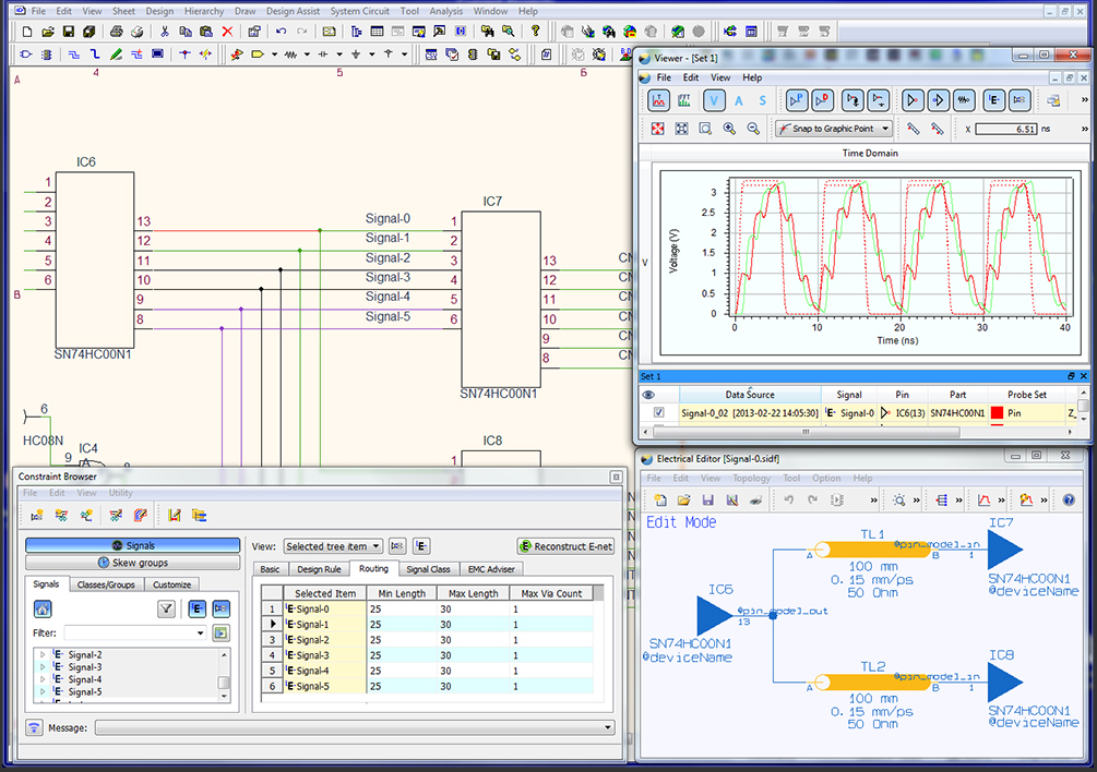
The CR-5000 EDA design suite provides the most advanced PCB design functionality currently available. It is constraints driven, from schematic capture through board layout, to the output of manufacturing data. More: This means that the rules you apply early...
A simple rotating display. Just spin and enjoy. While the "Air display" is rotating, it writes the message on the air. Because of the "persistence of vision", you will be able to read the message. The operation is super...
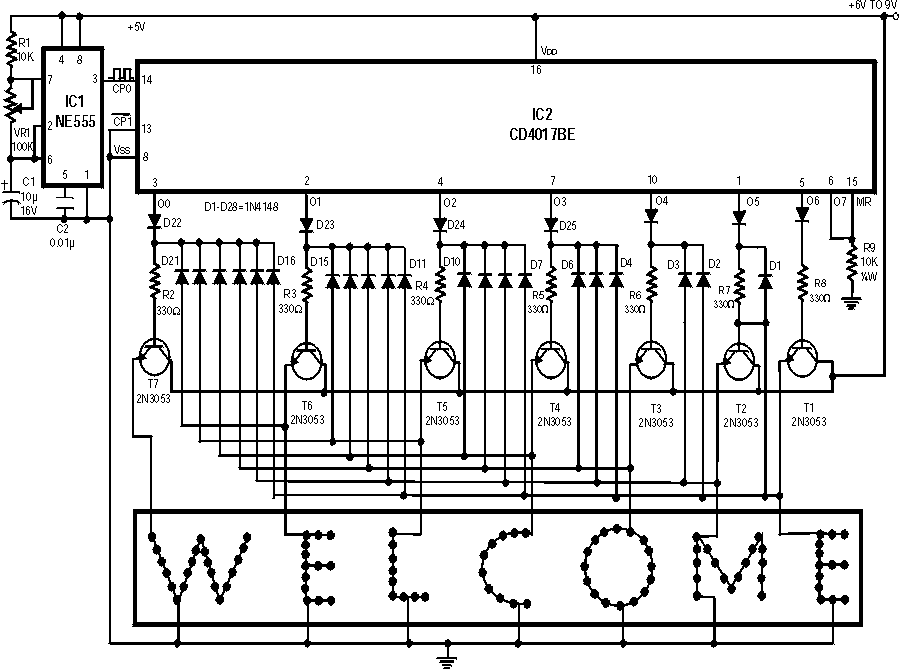
The servo driver is just simply two 4017 decade counters and lots of 0.1" headers. Only populate the A side headers; the B servo bank is optional and will require a few more header pieces. If you received 20...
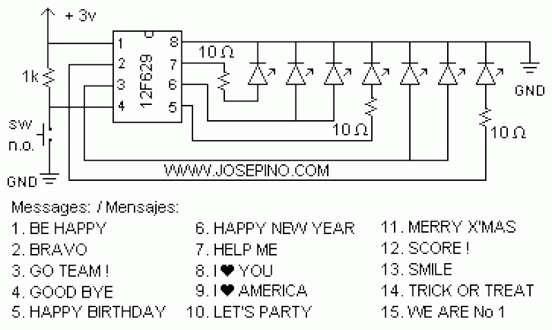
Light emitting diodes are advantageous due to their smaller size, low current consumption and catchy colours they emit. Here is a running message display circuit wherein the letters formed by LED arrangement light up progressively. Once all the letters...
This is a simple, programmable, autonomous and extensible LED matrix with the possibility of being controlled by a computer using a RS232 connection. Its basic modules are the Controller Board, the I/O Port expander boards and the LED matrix...
Most individuals seeking to modify and enhance their Spectrum often focus on the keyboard as a primary area for improvement. However, a straightforward replacement requires opening the computer, which can be discouraging for two main reasons. Firstly, this action...