LED Matrix board circuit
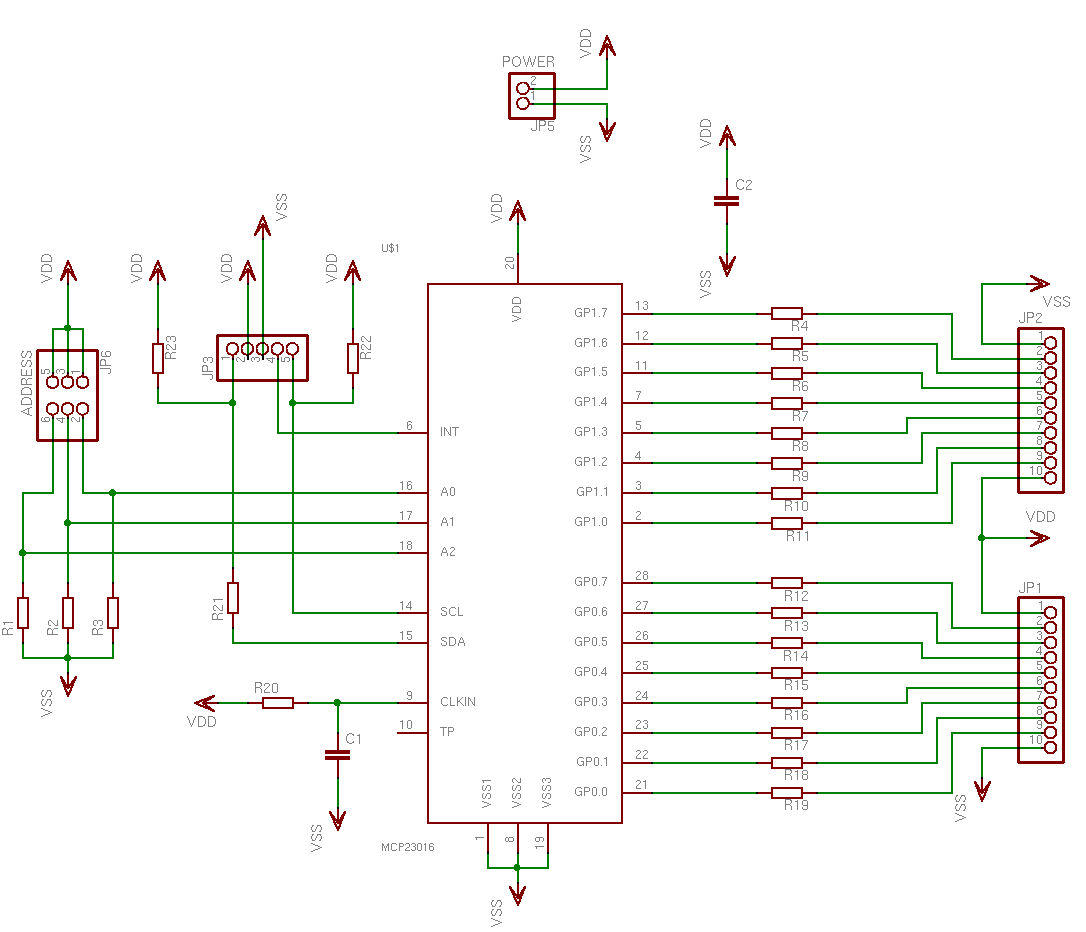
This is a simple, programmable, autonomous and extensible LED matrix with the possibility of being controlled by a computer using a RS232 connection. Its basic modules are the Controller Board, the I/O Port expander boards and the LED matrix cardboard support. The micro controller is a common Microchip PIC16F88, which has built-in support for I2C slave with a minimal support for I2C master, ASUART, PWM, multiplexed ADC and other interesting peripherals. The controller board also has an external 512kbit EEPROM to allow a bigger storage of drawing patterns and it uses the common MAX232 level shifter for easy interface with the PC RS232. The I/O port expander boards, which control both the vertical and horizontal lines of the matrix, were built around the MCP23016, which has 16 I/O lines and built-in I2C slave.
The described LED matrix system is a versatile and programmable display solution, designed to operate autonomously or under computer control through an RS232 interface. The system is composed of several key components that work together to facilitate the operation of the LED matrix.
The core of the system is the Controller Board, which integrates a Microchip PIC16F88 microcontroller. This microcontroller is equipped with various features, including I2C support, which allows it to communicate with peripheral devices. The I2C interface enables the microcontroller to act as an I2C slave, facilitating communication with the I/O port expander boards. Additionally, it offers minimal I2C master capabilities, allowing for potential future expansions.
The Controller Board is further enhanced by the inclusion of a 512kbit EEPROM, which serves as external memory for storing drawing patterns and configurations. This additional storage capacity is crucial for applications requiring complex or frequently changing visual displays.
For interfacing with a computer, the system utilizes a MAX232 level shifter, which converts the TTL logic levels from the microcontroller to RS232 voltage levels suitable for serial communication. This allows for a reliable connection to standard RS232 ports found on many computers.
The I/O Port Expander Boards are designed to manage the control signals for the LED matrix. Each board is based on the MCP23016, which provides 16 I/O lines and operates as an I2C slave. This configuration allows for efficient control of both the vertical and horizontal lines of the LED matrix, enabling the illumination of individual LEDs to create desired patterns and images.
Overall, the system architecture is modular, allowing for easy expansion and customization. The combination of the PIC16F88 microcontroller, EEPROM, MAX232 level shifter, and MCP23016 port expanders creates a robust platform for developing programmable LED matrix displays suitable for various applications, including art installations, information displays, and interactive projects.This is a simple, programmable, autonomous and extensible LED matrix with the possibility of being controlled by a computer using a RS232 connection. Its basic modules are the Controller Board, the I/O Port expander boards and the LED matrix cardboard support.
The micro controller is a common Microchip PIC16F88, which has built-in support for I2C slave with a minimal support for I2C master, ASUART, PWM,multiplexed ADC and other interesting peripherals. The controller board also has an external 512kbit EEPROM to allow a bigger storage of drawing patterns and it uses the common MAX232 level shifter for easy interface with the PC RS232.
The I/O port expander boards, which control both the vertical and horizontal lines of the matrix, were built around the MCP23016, which has 16 I/O lines and built-in I2C slave. 🔗 External reference
