
measurement Measuring large differential voltage

The high voltage power supply system is critical for the operation of the electron beam apparatus, and meticulous attention to the design is essential to ensure safety and functionality. The existing analog voltage regulation system, while functional, presents limitations in terms of precision and adaptability. The proposed transition to a microcontroller-based control system aims to enhance the performance and reliability of the voltage regulation process.
The feedback mechanism is a crucial aspect of maintaining the desired output voltage. The 50k feedback resistor (R1) plays a pivotal role in this system, as it provides a reference signal to the voltage regulator. Care must be taken to maintain the integrity of the existing resistance network to avoid introducing errors into the voltage measurement process. This network's connection to the analog kV meter necessitates a non-intrusive approach to the redesign.
Incorporating a high impedance voltage divider using 11 megohms ensures that the feedback signal remains accurate while preventing any significant loading effects on the feedback loop. The choice of a unity gain differential amplifier or a high impedance instrumentation amplifier is appropriate, as it allows for precise signal conditioning without introducing additional noise or distortion. The use of an isolating DC-DC power supply is critical in maintaining safety and preventing ground loops, especially when dealing with high voltage systems.
The implementation of the TI ISO124 isolation amplifier is a strategic choice to safeguard the microcontroller from high voltage levels while ensuring that the feedback signal can be accurately processed. The subsequent scaling of the signal through a potentiometer before it reaches the microcontroller's ADC will allow for fine-tuning of the measurement and control process, thereby enhancing the overall functionality of the system.
This design approach not only modernizes the control system but also maintains the integrity of the existing high voltage power supply architecture, ensuring that the electron beam system operates safely and effectively.A high voltage power supply for an electron beam system. The voltage regulator is an old analog system that works via a simple comparator and reference signal from a POT. My problem is the feedback voltage from the high voltage tank (tank meaning large steel oil filled tank with all HV components inside) is upward of 124 volts DC and is floating in respect to ground.
The feedback signal comes from a 50k resistor which is part of a large resistance network inside the tank. Part of that network also runs to an analog 0-1mA meter that is a kV meter so I don`t want to mess with the resistance. I am trying to replace the analog controller with a microcontroller (ATmega) to replace the closed loop analog control with digital control.
I don`t want to mess with the resistance network inside the tank so this has to piggyback existing system and not unbalance the resistance. Below is an overly simplified schematic of the power supply. As you can see R1 is the feedback resistor, two wires are taken from each of its terminals and run to the voltage regulator.
R3 represents beam current measurement and overload protection (different circuit). The ground is chassis/earth ground. R2 represents the numerous resistors inside the tank from the negative side of the power supply. R4 and R5 is my planned divider to a difference amp (ignore the TL801 part number). My idea is to use a high impedance divider using 11 megs of resistance and then feeding that scaled down signal into a unity gain difference amplifier or high impedance instrumentation amplifier. The amplifier would be powered from an isolating DC-DC power supply and the signal isolated via an isolation amplifier ( TI ISO124 ).
From there I can scale it further using a POT to the uC ADC. Any thoughts 🔗 External reference
Related Circuits

Sometimes it is necessary to power a circuit from a battery where the required supply voltage falls within the discharge curve of the battery. If the battery... Powering a circuit from a battery involves understanding the discharge characteristics of the...
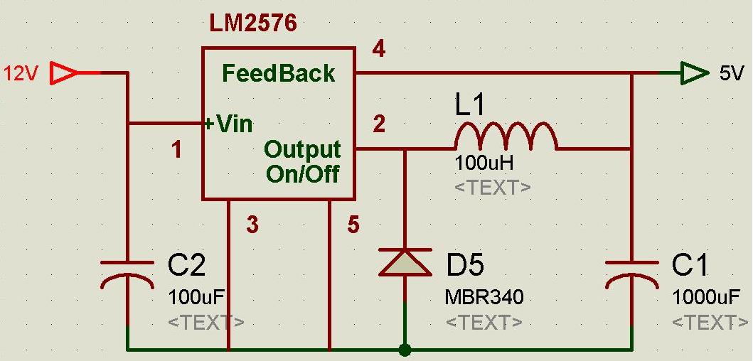
A regulated and noise-free power supply voltage is essential for microcontrollers and other components such as amplifiers, filters, and GPS devices. Voltage surges in the supply voltage can permanently damage embedded systems. A voltage regulator must maintain the output...
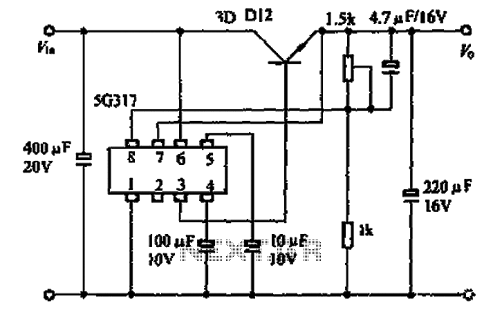
The 5G317 is an integrated voltage regulator circuit used in wiring applications for televisions. The maximum input voltage for the 5G317 should be less than 25V, while the output voltage ranges from 10V to 18V. The maximum output current,...
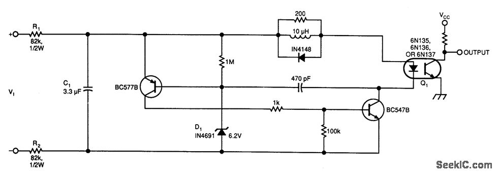
This circuit below illustrates a simple voltage-controlled oscillator (VCO) connected to instrumentation via an optoisolator. The voltage-controlled oscillator (VCO) circuit operates by generating a periodic waveform whose frequency is determined by an input control voltage. The primary components of this...
This site serves as a collection of useful information that the author wishes to retain, with the occasional inclusion of pages that may be of interest to others. The author has documented the retrofit of the Boxford 125 TCL...
It is widely recognized that while a large loop feedback from the amplifier output stage to the preceding stage can enhance frequency response and reduce harmonic distortion indicators in an amplifier, it may adversely affect the transient characteristics and...