
Integrated voltage regulator circuit diagram 5G317 TV application

The 5G317 voltage regulator circuit is specifically designed for applications in compact television sets, particularly those with screen sizes of 9 inches and 12 inches. The circuit operates efficiently with a maximum input voltage of 25V, ensuring compatibility with various power supply configurations. The output voltage is adjustable between 10V and 18V, making it versatile for different operational requirements.
The internal architecture of the 5G317 includes a reference voltage source, a current amplification section, and a feedback mechanism that stabilizes the output voltage against fluctuations in input voltage or load conditions. The built-in potentiometer (1.5k) provides a means to fine-tune the output voltage, allowing for precise control based on the specific needs of the television circuitry.
The maximum output current capability of 30mA without an external regulator is significant for low-power applications, while the potential for an output current of up to 2A when paired with an external regulator expands the usability of the 5G317 in more demanding scenarios. This feature is particularly beneficial for driving components that require higher current levels, such as audio amplifiers or display backlighting.
The 8-pin dual in-line package (DIP) design of the 5G317 allows for easy integration into printed circuit boards (PCBs), facilitating efficient assembly processes in manufacturing environments. The compact size of the IC, combined with its integrated functionality, contributes to reduced component count and lower overall production costs, making it an attractive choice for television manufacturers aiming to deliver cost-effective yet reliable products.
Overall, the 5G317 voltage regulator circuit is a robust solution for voltage regulation in small television applications, combining flexibility, efficiency, and simplicity in design. As shown in FIG 5G317 TV is integrated voltage regulator circuit wiring applications. In the application, the maximum input voltage 5G317 should be less than 25V, output voltag e 5G317 is 10 ~ 18V, maximum output current (no external regulator) is 30mA, resistance 1 Euro. Icon Line output current up to 2A, the European regulator 1.5k potentiometer can change the output voltage. 5G317 IC is 8-pin dual in-line package. It is designed for turning 9 inches and 12 inches TV production integrated regulator with a reference sample, the current amplification section, plus the regulator and a few elements to enable parties to use inexpensive.
Related Circuits
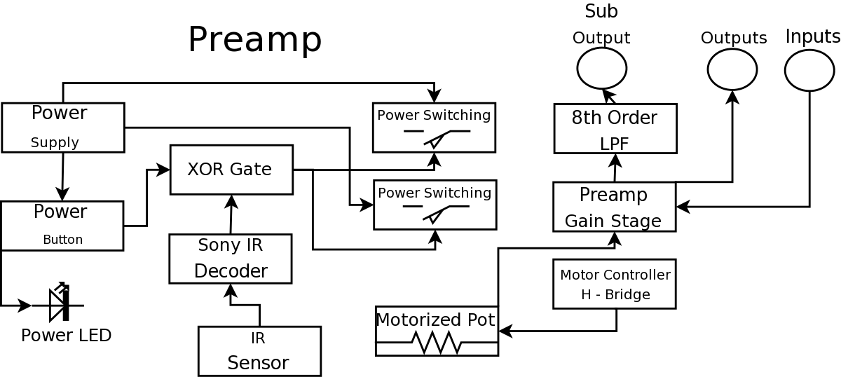
During a Digital Projects Lab, the professor suggested incorporating more circuit-level work into a project. To achieve this, a preamplifier was designed, which included an infrared (IR) remote control to replace a previously built version. The earlier preamplifier functioned...
A step-down circuit is utilized to approximately halve the RMS voltage between the line input and the inductive load (L1), as illustrated in the circuit diagram below. A turn-on delay of about 7 ms is achieved through the combination...
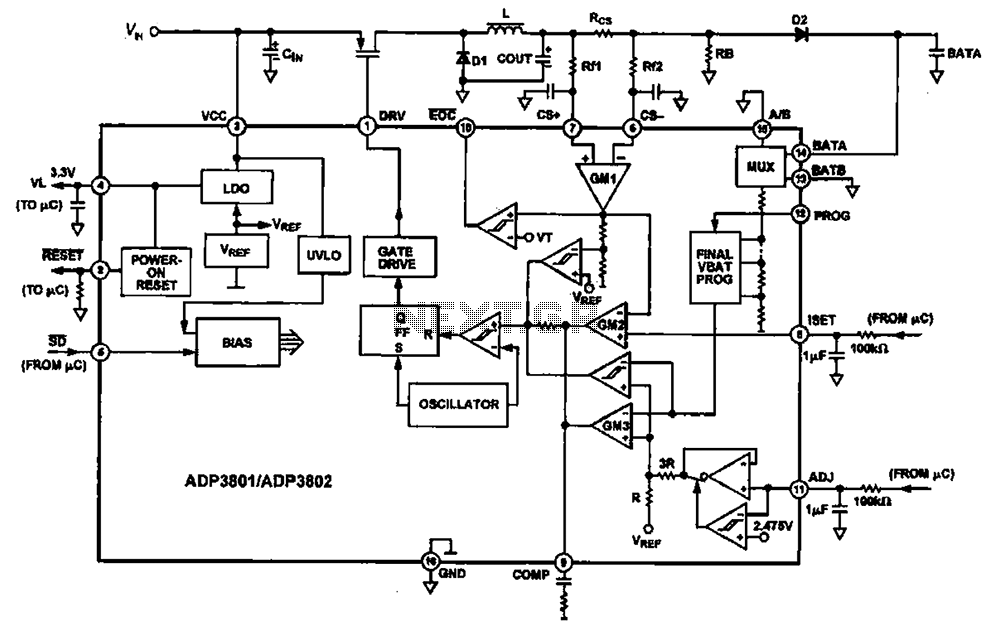
Charging circuit diagram for personal work based on the operating principle of ADP3801/3802 charging circuit. The ADP3801/3802 is a highly integrated battery charger controller designed for Li-ion and Li-polymer batteries. The charging circuit typically consists of several key components including...

The circuit is designed to regulate a dual power supply that provides +12V and -12V from the AC mains. Such a power supply is an essential tool for an electronic hobbyist's workbench. The schematic of the circuit includes components...
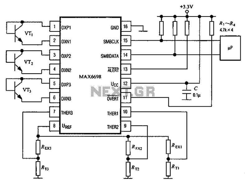
Channel 7 presents a circuit diagram of a smart temperature sensor using the MAX6698. This circuit includes three transistors (VT1, VT2, and VT3) and three thermistors (RT1, RT2, and RT3). An internal reference voltage source is provided via resistors...
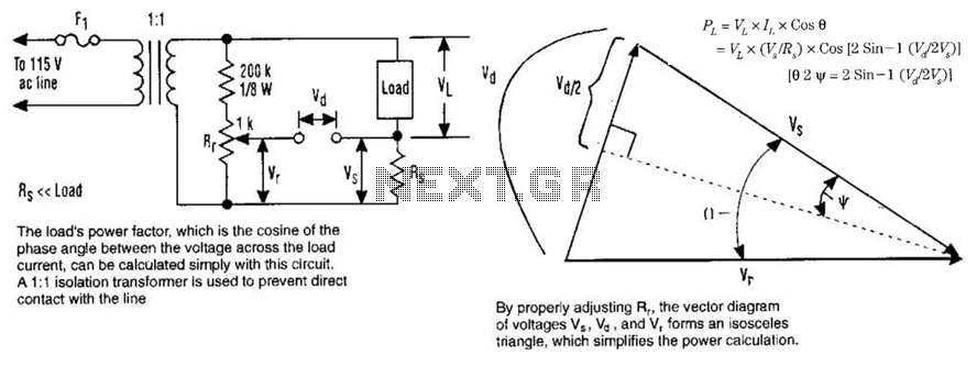
The load's power factor, defined as the cosine of the phase angle between the voltage across the load and the load current, can be calculated using this circuit. An isolation transformer with a 1:1 ratio is employed to prevent...