
Medium Wave Active Antenna

The described circuit functions as an active preamplifier specifically tailored for receiving medium wave signals. It utilizes a telescopic whip antenna, which is known for its compact design and ability to receive a wide range of frequencies. The operational bandwidth of the circuit spans from 550 KHz to 1650 KHz, making it suitable for various medium wave broadcasting stations.
The preamplifier's performance is adjustable through two main components: RV1 and RV2. RV1, a gain control potentiometer, allows the user to fine-tune the amplification level. This feature is crucial for optimizing the reception of weak signals while preventing distortion from stronger signals. By adjusting this component, the circuit can adapt to varying signal strengths, providing flexibility for different listening environments.
RV2 serves as the tuning voltage control, utilizing a 10k potentiometer connected to a 12 Volt power supply. This component allows for the adjustment of the circuit's tuning characteristics, enabling the user to select the desired frequency within the specified range effectively. Proper tuning is essential for maximizing signal reception and minimizing interference from unwanted frequencies.
An important aspect of this circuit is its capability to operate on multiple bands. The inclusion of 330uH coils allows for tuning adjustments, which can be modified to accommodate different frequency bands. To facilitate this, external switches or relays can be integrated into the circuit design. These components would enable the user to easily switch between different coil values, thereby altering the circuit's operational frequency range without the need for extensive reconfiguration.
Overall, the circuit is designed to provide enhanced signal reception for medium wave frequencies, with adjustable gain and tuning capabilities that allow for versatile operation across various bands. This design is beneficial for applications where improved antenna performance is desired, such as in radio communication, broadcasting, and amateur radio setups.This circuit is designed to amplify the input from a telescopic whip antenna. The preamplifier is designed to cover the medium waveband from about 550Khz to 1650Khz. The tuning voltage is supplieb via RV2, a 10k potentiometer connected to the 12 Volt power supply. RV1 is the gain control allowing weak signals to be amplified or strong signals to be attenuated. Finally this active antenna can be used on other bands by changing the values of the 330uH coils. To perform on multiple bands switches or relays can be used to change the value of the coils. 🔗 External reference
Related Circuits
Antennas that are much shorter than 1/4 wavelength present a very small and highly relative impedance that is dependent on the received frequency. It is difficult to match impedances over a decade of frequency coverage. Instead, input stage Q1...
The goal is to transmit additional information through the use of articles. If there are any issues related to article content, copyright, or other concerns, please contact us via email at [email protected] within 15 days. The content will be...
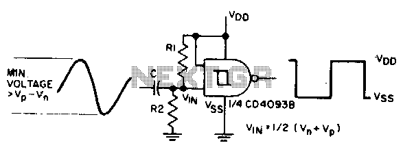
The sine input is AC coupled by capacitor C. Resistors Rl and R2 bias the input midway between Vn and Vp, which are the input threshold voltages. This configuration is designed to provide a square wave at the output. The...

The following diagram represents the schematic of an Active Tone Control circuit, commonly referred to as "ACTOR." The Active Tone Control circuit is an electronic audio circuit designed to enhance the loudness of audio signals by adjusting bass and...
This document presents plans for a simple ground plane antenna that is effective in the FM band (88-108 MHz). It is constructed from a small plastic disk. The 6 x 6 loop antenna, designed by Graham Maynard, is highlighted...
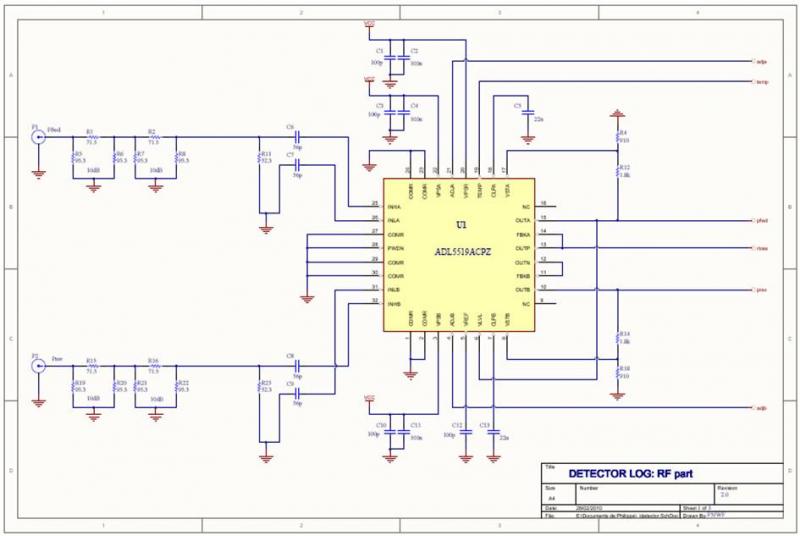
The ADL5519 is particularly focused on bandwidth, specified up to 8 GHz, though it remains usable at 10 GHz with reduced dynamic range. It features two channels, allowing for the measurement of power transmitted to the antenna and the...