
Sine wave-to-square wave converter

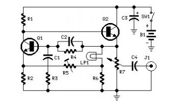
The circuit utilizes an AC coupling technique through capacitor C, which allows only the alternating current (AC) component of the input signal to pass while blocking any direct current (DC) offset. This is crucial in applications where the input signal may have a DC component that could affect the performance of subsequent stages in the circuit.
Resistors Rl and R2 are configured to set the bias point of the input signal. By positioning the bias point between Vn (the negative threshold voltage) and Vp (the positive threshold voltage), the circuit ensures that the input signal oscillates around a midpoint that facilitates the desired output waveform. This midpoint biasing is essential for achieving optimal signal processing, as it allows the signal to swing fully between the thresholds without clipping.
The output of the circuit is designed to generate a square wave. This is typically achieved through the use of a comparator or a Schmitt trigger configuration. The square wave output is characterized by rapid transitions between high and low states, making it suitable for applications such as digital signal processing, timing circuits, or clock generation.
In summary, the combination of AC coupling through capacitor C and the biasing arrangement of resistors Rl and R2 enables the circuit to effectively convert a sine wave input into a square wave output, ensuring proper signal integrity and performance for subsequent electronic stages.The sine input is ac coupled by capacitor C; Rl and R2 bias the input midway between Vn and Vp, the input threshold voltages to provide a square wave at the output.
Related Circuits
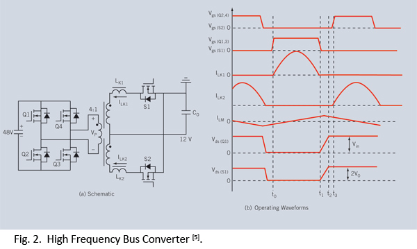
Distributed power systems are commonly used in telecommunications, networking, and high-end server applications, utilizing a 48 V bus voltage derived from the telecom industry. This 48 V bus supplies several isolated point-of-load (POL) converters that power the end loads,...
Set R5 to read 1V RMS on an audio millivoltmeter connected to the output with R7 rotated fully clockwise, or to view a sine wave of 2.828V peak-to-peak amplitude on the oscilloscope. An audio amplifier is an electronic device...
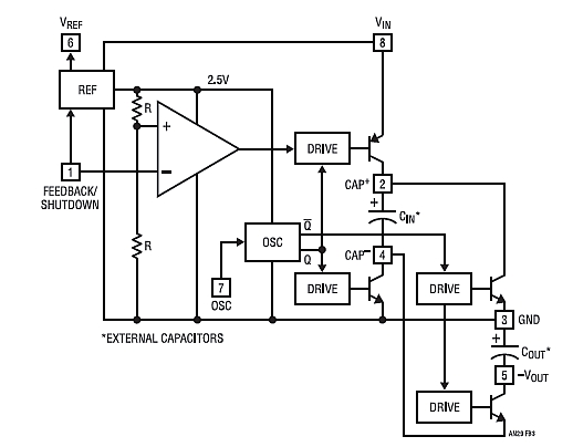
Chapter 4, part five of a five-part series titled "Some Thoughts on DC/DC Converters," authored by the late Jim Williams and Brian Huffman, is included in Volume II of the book "Analog Circuit Design-- Immersion in the Black Art...
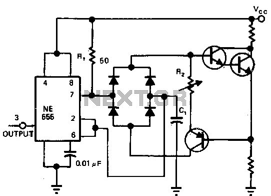
Utilizing a single current source for both the charge and discharge paths in this circuit guarantees that the rise and fall times at the capacitor terminal are identical. A Darlington pair is employed to ensure consistent biasing of the...
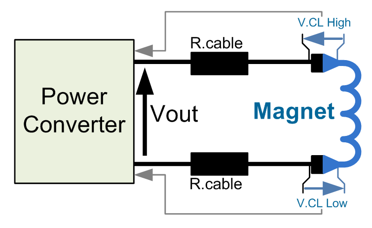
This power converter is utilized in the LHC machine to supply power to superconductive magnets. It is situated in the underground installation of the LHC, in proximity to the loads to minimize cable losses. The voltage source employs a...
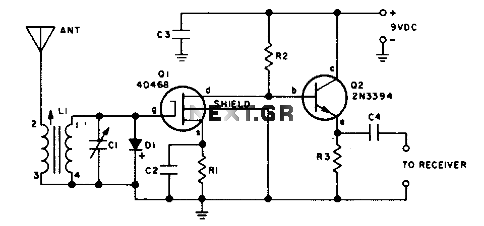
This two-transistor preselector provides up to 40 dB gain from 3 to 30 MHz. Q1 (MOSFET) is sensitive to static charges and must be handled with care. The two-transistor preselector circuit is designed to amplify signals within the frequency range...