
Memory save on power-down

The circuit described involves a power management system that utilizes both a main output and an auxiliary output to ensure reliable operation of memory components within an electronic system. The main output serves as the primary power source for the overall system, while the auxiliary output specifically provides power to the memory module.
The memory store pin is crucial in this configuration, as it facilitates communication between the main output and the memory. When the system experiences a power failure or significant voltage drop, the main output transitions to a low state. This condition signals the memory to execute a store operation, effectively saving critical data before complete power loss occurs.
Following the transition of the main output to low, the auxiliary output is designed to drop out, ceasing its power delivery to the memory. This sequential operation ensures that the memory has sufficient time to complete its data storage processes, thus enhancing data integrity and preventing potential loss.
In terms of implementation, this circuit may include a voltage supervisor or comparator that monitors the main output voltage. Upon detecting a drop below a predetermined threshold, the supervisor can trigger the necessary actions to transition the main output low and subsequently disengage the auxiliary output. Components such as capacitors may be included to provide temporary power during the transition period, allowing the memory to complete its operations without data loss.
Overall, this power management system is essential for applications requiring data retention during power interruptions, ensuring that memory components operate reliably and efficiently under varying power conditions.The auxiliary output powers the memory, while the main output powers the system and is connected to the memory store pin. When power goes down, the main output goes low, commanding the memory to store. The auxiliary output then drops out.
Related Circuits

The discharge process in the memory circuit is an instantaneous action, followed by a delay reset circuit. When the input signal is activated, the circuit opens. Once the input signal is removed, the circuit begins counting after a predetermined...
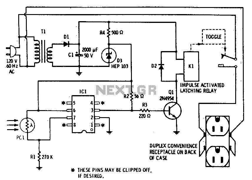
This device enables remote control of AC-powered appliances by utilizing the beam of a flashlight as a triggering mechanism. A key feature of this gadget is its memory function; activating it once supplies power to the device, and it...
If expecting an important visitor but needing to step out for a moment, an electronic doorbell memory can be useful to check if someone rang while away. It may not indicate if the expected visitor arrived, but a quick...

The CODE and CONST memory classes are generally stored in ROM, which can be either off-chip or on-chip. The CODE memory class is utilized for the actual program code, while the CONST memory class is designated for constant variables...
When the door is opened, SW1 closes, powering the circuit and turning on the lamp. C1 begins to charge slowly through R1, and when the voltage at pins #2 and #6 of IC1 reaches 2/3 of the supply voltage,...
A keyboard is typically connected using a matrix configuration of rows and columns. For example, a 12-button keyboard requires 3 to 4 digital inputs from a microcontroller. However, it is possible to construct a keyboard that connects to a...