
Car Battery Saver Circuit

The described circuit functions as an automatic lamp control system activated by a door switch. The primary components include a switch (SW1), a capacitor (C1), a resistor (R1), and an integrated circuit (IC1) that contains a flip-flop and a comparator. Upon opening the door, SW1 closes, initiating the circuit and illuminating the lamp. The capacitor C1 charges gradually through the resistor R1, which controls the charging rate. The specific voltage threshold of 2/3 of the supply voltage at the comparator pins of IC1 is crucial for determining when the flip-flop state changes.
Once the voltage threshold is achieved, the internal comparator of IC1 triggers a change in the flip-flop state, resulting in a drop in voltage at pin #3 to zero. This action turns off the lamp, effectively creating a delay in illumination that is dependent on the charging time of C1. The lamp will remain off as long as the door is closed, ensuring energy efficiency and preventing unnecessary illumination.
The three-terminal configuration allows for easy integration with existing door switches and lamps. The two terminals connect the circuit in series with the lamp and the door switch, while the third terminal connects to a 12V power supply, providing necessary voltage for operation. Additionally, the circuit includes a bypass option through a standard switch, which permits the lamp to remain on continuously, regardless of the door's position. This feature can be useful in scenarios where constant light is desired, such as during cleaning or maintenance activities.
The use of dotted lines in the schematic indicates the optional bypass connection, clearly distinguishing it from the main circuit path. This design approach enhances the versatility of the lamp control system, catering to various user needs while maintaining straightforward operation and installation. Overall, this circuit exemplifies a practical application of electronic components to achieve an automated lighting solution that responds to user actions.When the door is opened, SW1 closes, the circuit is powered and the lamp is on. C1 starts charging slowly through R1 and when a voltage of 2/3 the supply is reached at pins #2 and #6 of IC1, the internal comparator changes the state of the flip-flop, the voltage at pin #3 falls to zero and the lamp will switch-off. The lamp will remain in the off state as the door is closed and will illuminate only when the door will be opened again. The final result is a three-terminal device in which two terminals are used to connect the circuit in series to the lamp and the existing door-switch. The third terminal is connected to the 12V positive supply. The circuit can be bypassed by the usually existing switch that allows the interior lamp to illuminate continuously, even when the door is closed: this connection is shown in dotted lines.
🔗 External reference
Related Circuits
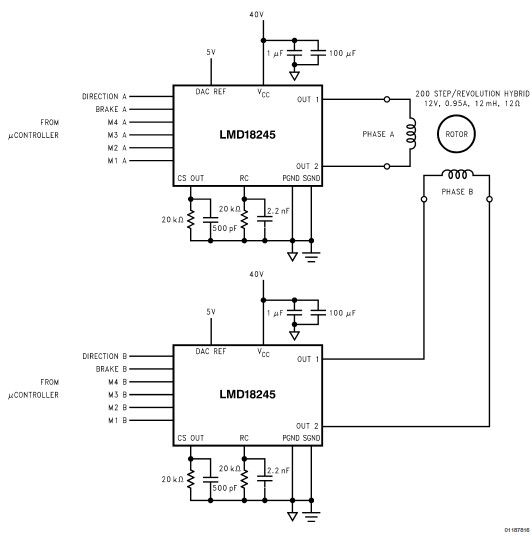
LMD18245 bipolar stepper motor driver circuit design using few electronic parts The LMD18245 is a versatile bipolar stepper motor driver designed to control stepper motors with precision and efficiency. This circuit utilizes a minimal number of electronic components, making it...
Solar panels operate at optimal parameters when positioned at the ideal angle to the sun. This alignment is achieved by rotating the solar panels to track the sun's movement. A DIY solar tracker system can be constructed using an...
The VU meter is categorized into two types: those that use needle instruments and those that employ LED columns. A VU meter sound level meter is essential for both tube amplifiers and integrated amplifiers. Currently, there are numerous integrated...
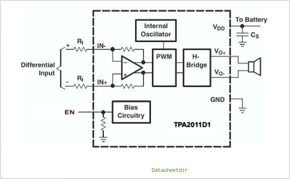
The TPA3007D1 is a 6.5-W mono bridge-tied load (BTL) class-D audio power amplifier featuring high efficiency, which eliminates the need for heat sinks. This amplifier can drive 8-ohm speakers with only a ferrite bead filter required to reduce electromagnetic...

This design is for a charger circuit suitable for lead-acid batteries, including flooded, gel, and AGM types. The circuit features a simple design. The automatic function means that this charger will stop charging automatically when the battery voltage reaches...
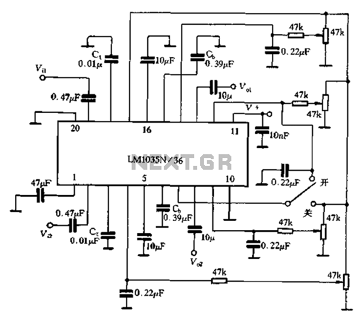
The circuit includes a loudness compensation control terminal at pin 7, which, when combined with the DC control voltage, forms a simple loudness compensation mechanism that enhances bass response. When the loudness control switch is in the OFF position,...