
metal detector 555 timer

The metal detector circuit utilizes the 555 timer IC in astable mode to generate a frequency that is modulated by the presence of metal objects. The basic configuration includes the 555 timer, resistors, capacitors, and a speaker or buzzer to provide audio feedback when metal is detected.
In the schematic, the 555 timer is connected with two resistors and a capacitor to set the oscillation frequency. When metal is introduced into the detection area, it alters the inductance of a coil connected to the circuit, which in turn affects the timing characteristics of the 555 timer. This change in frequency is perceived as a change in tone or pitch from the output device, alerting the user to the presence of metal.
The circuit may also include a potentiometer to allow for sensitivity adjustments, enabling the user to fine-tune the detection range based on environmental conditions. Additionally, a simple LED indicator can be integrated to provide a visual cue alongside the audio signal, enhancing user experience.
Overall, this metal detector project represents an accessible and educational introduction to basic electronics and signal processing, demonstrating the practical application of the 555 timer IC in detecting metallic objects.This metal detector electronic project schematic circuit is designed using a simple 555 timer integrated circuit. As you can see in the schematic circuit, this metal detector electronic project requires few external electronic parts.
🔗 External reference
Related Circuits
A simple two tone water alarm that is light enough to be worn on the upper arm of a sleeper is described. It uses two LMC555 CMOS timer chips followed by a complimentary pair of emitter followers to drive...
The 555 circuit below is a flashing bicycle light powered with three C or D cells (4.5 volts). The two flashlight lamps will alternately flash at an approximate 1.5 second cycle rate. Using a 4.7K resistor for R1 and...
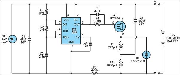
The following circuit illustrates a 6/12/24V Lead Acid Battery Charger Circuit Diagram. Features: It is essentially a high-voltage pulse generator. The circuit diagram for a 6/12/24V Lead Acid Battery Charger is designed to efficiently charge lead-acid batteries of varying voltages....
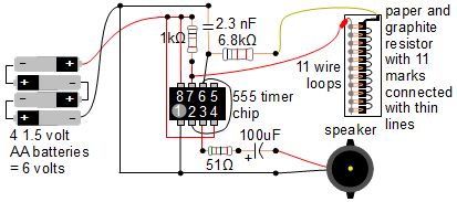
A simple music instrument/keyboard is created using a 555 timer chip circuit, a piece of paper, and a pencil. The project includes a more advanced automatic music player that utilizes a playing head and a long sheet of paper...

This lie detector circuit provides two readings: one for difficult questions and another for the subject's general emotional state. Two flexible, uninsulated wires wrapped around the fingers or wrist can serve as electrodes. Each change in resistance, and consequently...
555 Timer Sound Effects Videos 1. This project involves creating a light theremin using a 555 timer. It is suitable for spooky Halloween effects. 3. A film countdown timer is included. 4. A UHD chessboard timer is also featured....