
Metal Detector

The metal detector circuit primarily consists of an oscillator, a frequency-sensitive inductor, and a ceramic filter, all of which work in conjunction to detect metallic objects. The oscillator generates a stable frequency signal, which is critical for the operation of the circuit. The frequency of this oscillator is set to 455 kHz, a common frequency used in metal detection applications due to its effective balance between sensitivity and noise rejection.
Inductor Ll is a crucial component of the circuit, as it creates a magnetic field that responds to nearby metallic objects. The design of this inductor, specifically its dimensions and the number of turns, greatly influences the circuit's performance. A 4-inch diameter coil with approximately 10 turns of #26 wire is recommended to achieve optimal inductance and sensitivity. The choice of wire gauge is important, as it affects the resistance and quality factor of the coil, ultimately impacting the circuit's efficiency.
The ceramic filter FILT1 serves to isolate the desired frequency range, allowing the circuit to focus on the frequency changes induced by the presence of metal. This selective bandpass filter enhances the circuit's ability to discern between the signal generated by the oscillator and any extraneous noise, ensuring that only relevant frequency variations are registered on the meter Ml.
To ensure proper operation, a frequency counter is employed to measure the oscillation frequency and to facilitate adjustments to inductor Ll. This verification process is essential, as it confirms that the oscillator is functioning within the intended frequency range, thus ensuring reliable detection of metallic objects. Proper calibration of the circuit is vital for achieving maximum sensitivity and accuracy in detecting metals, making the frequency counter an indispensable tool in the setup and maintenance of the metal detector circuit. Using an oscillator running at 455 kHz, the metal-detector circuit produces an indication on the meter Ml. When the oscillat or frequency changes because of metal in the field of Ll, the change will show as an increase or decrease in frequency, which produces a charge in the meter reading. The ceramic filter FILT1 produces a selective bandpass that yields this effect. Ll can be a 4" diameter coil wound on a suitable plastic form. About 10 turns of #26 wire are required. Use a frequency counter to adjust Ll and verify that Ql is operating on or near 455 kHz.
Related Circuits
The schematic presented is a circuit designed for monitoring plant watering, also known as a dry soil detector. Indoor plants, whether in homes or offices, require more attention compared to outdoor plants. Due to busy schedules, it is common...
This circuit responds to the presence of any conductive object, including humans. It does not detect object movement but can function as a proximity sensor. The circuit operates on the principle of capacitive sensing, utilizing a capacitor to detect changes...
This is a circuit which I originally included in my book, 22 Tested Transistor Projects, published by Babani Press in 1976 (ISBN 0 900162 63 S). It is one I had great fun with. It uses the PUT Complimentary...
This photocell is best mounted at tie level between the rails. The variable resistor adjusts the sensitivity of the circuit. This circuit can be powered by either 6 or 12 volts - BE SURE to use the proper relay;...
This circuit detects motion within approximately 5 inches of a piezo-ceramic element ultrasonic transducer. The detection distance is much smaller than obtainable with other ultrasonic techniques; however, it only requires a single transducer, as opposed to the two-transducer arrangement...
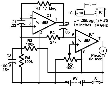
This circuit utilizes a 1458 dual operational amplifier (op-amp) to create a radar detector. Capacitor C1 serves as the sensor for the radar signal. The first op-amp is configured as a current-to-voltage converter, while the second op-amp functions as...