
plant watering watcher dry soil detector

The plant watering watcher circuit employs a simple yet effective design to ensure that indoor plants receive adequate moisture. It typically consists of two metal probes that serve as moisture sensors. When inserted into the soil, these probes complete a circuit that allows current to flow based on the moisture level present. In dry soil conditions, the resistance between the probes increases, leading to a voltage change that is detected by the circuit.
The core component of this circuit is the operational amplifier or comparator, which compares the voltage from the probes against a reference voltage set by the variable resistor. When the soil moisture level drops below the predefined threshold, the output of the comparator changes state, triggering the buzzer and illuminating the LED. This visual and auditory alert serves as a reminder for the user to water the plants.
The 300K variable resistor plays a crucial role in adjusting the sensitivity of the circuit. By tuning this resistor, the user can set the threshold at which the circuit activates. This adjustability is essential, as different types of soil and plant species may require varying moisture levels. The calibration process outlined ensures that the circuit operates accurately, providing reliable alerts when the soil becomes too dry.
In summary, this plant watering watcher circuit is an essential tool for anyone managing indoor plants. Its straightforward design, combined with adjustable sensitivity, makes it an effective solution for preventing plant neglect and ensuring optimal growth conditions.The schematic shown here is a circuit of plant watering watcher or dry soil detector. The plants located in your home or office wants more care as compare to the plants outside. We often forget to water the plants in our home and offices due to load of work and as a result our plants become dry and unhealthy. The circuit shown here is a very usefu l device for reminding to water your plant. The circuit will give a beep and activate an LED when the two probes will not detect any moisture in the soil. The 300K variable resistor is used to activate the buzzer and LED on the desired level of soil dryness.
To adjust the circuit, insert the two probes when the soil is moist and slightly adjust the variable resistor until the LED and buzzer goes off, after that take out one probe from the soil, if the LED and the buzzer will activate that means your circuit is adjusted and ready for use. 🔗 External reference
Related Circuits
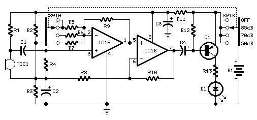
This circuit is designed to signal the exceeding of a fixed threshold in room noise through a flashing LED. Three fixed levels are selectable: 50, 70, and 85 dB. Two operational amplifiers provide the necessary gain for sounds captured...
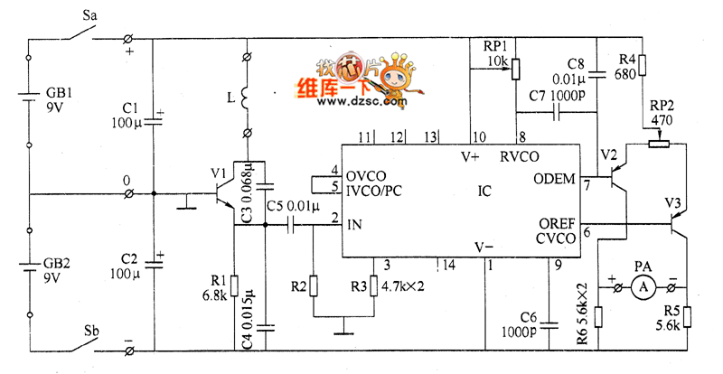
The metal detector circuit comprises several key components, including a power circuit, a sine wave oscillator, a PLL (phase-locked loop) circuit, and a hybrid amplifying circuit. The power circuit is made up of batteries GBI and GB2, filter capacitors...
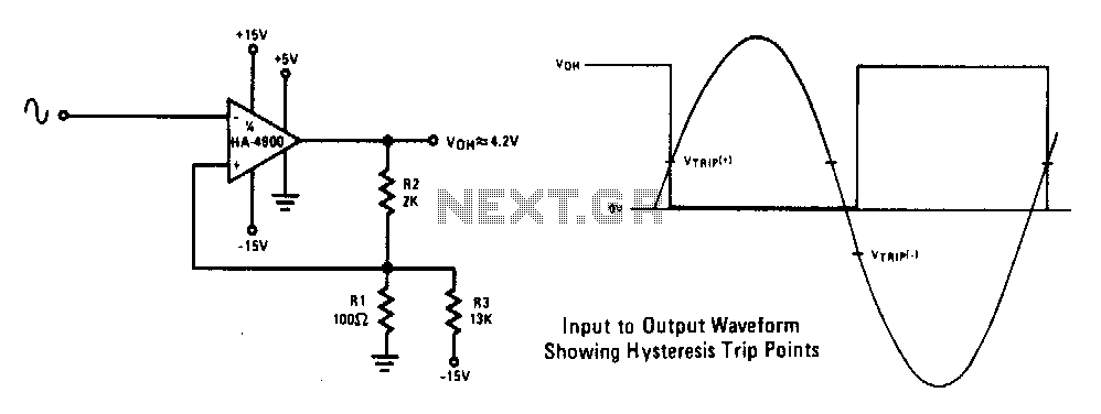
This circuit features a 100 mV hysteresis, suitable for applications demanding rapid output transition times despite slow input signals. The hysteresis loop minimizes false triggering caused by noise on the input. The accompanying waveforms illustrate the trip points established...
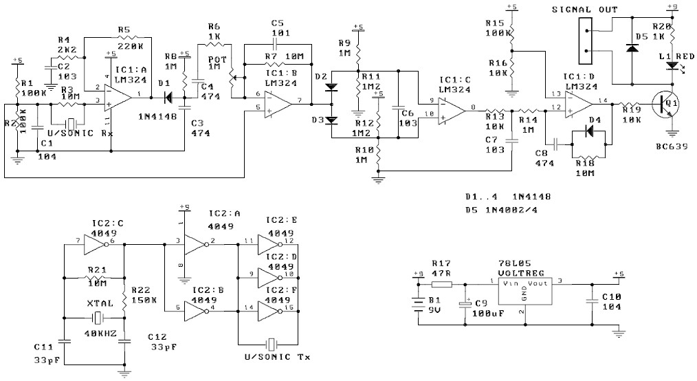
The circuit described exhibits high sensitivity to movement, capable of detecting even slight air movements such as hot air rising or wind blowing when the trimpot is adjusted to a sensitive position. The transmitter emits a continuous ultrasonic tone...
This ion detector circuit is designed to sense static charges and free ions present in the air. It is capable of detecting the presence of free ions, static electricity, or high voltage leakage. The project utilizes a short whip...
The circuit employs an infrared (IR) phototransistor, designated as Q1, to sense the IR output signal from a remote control. The output from Q1 is then amplified by a PNP transistor, labeled Q2, which activates LED1. This illumination indicates...