
metal detector circuit

The low-cost metal detector circuit is primarily based on the principles of oscillation and frequency modulation. The core component is a single transistor configured as a Colpitts oscillator, which generates a stable oscillation frequency determined by the values of the inductance (coil) and capacitance used in the circuit. The transistor amplifies the oscillation signal, which is then transmitted to the pocket radio.
The operation begins by tuning the pocket radio to the specific frequency of the Colpitts oscillator. This tuning is crucial as it establishes the baseline condition where both devices are harmonized at the same frequency, resulting in a silent state due to destructive interference. The setup requires careful adjustment of the radio's tuning dial until no sound is heard, confirming that the frequencies are aligned.
When the metal detector is moved close to a metallic object, the presence of the metal alters the inductance of the coil in the oscillator circuit. This change in inductance shifts the frequency of the oscillation produced by the Colpitts oscillator. Because the radio remains tuned to the original frequency, the two frequencies are no longer in sync, leading to constructive interference. This change manifests as a hissing sound from the radio, providing an audible signal that metal has been detected.
This simple yet effective design highlights the essential relationship between inductance and frequency in oscillatory circuits and demonstrates a practical application of these principles in metal detection. The circuit's reliance on readily available components, such as a single transistor and an old radio, underscores its accessibility and cost-effectiveness for hobbyists and educational purposes.This is the circuit diagram of a low cost metal detector using a single transistor circuit and an old pocket radio. This is nothing but a Colpitts oscillator working in the medium band frequency and a radio tuned to the same frequency.
First the radio and the circuit are placed close. Then the radio is tuned so that there is no sound from radio. In th is condition the radio and the circuit will be in same frequency and same frequencies beat off to produce no sound. This is the set up. When the metal detector circuit is placed near to a metal object the inductance of its coil changes, and so do the frequency of oscillations.
Now the two frequency will be different, there will be no canceling and radio produces a hissing sound. The metal is detected. 🔗 External reference
Related Circuits
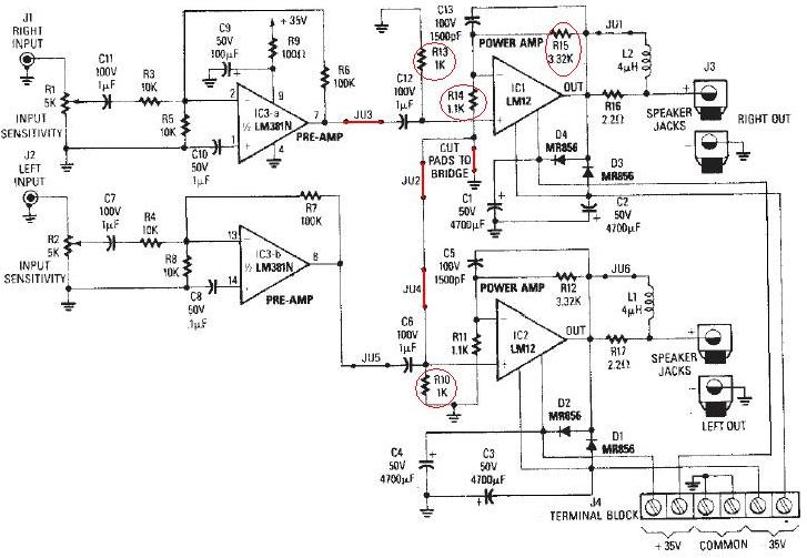
The LM12 audio amplifier circuit is designed to deliver high output power for loads with impedances of 4 ohms or 8 ohms. The maximum output power achievable by this amplifier is approximately 60 watts for a 4-ohm load and...

This simple device enables two computers to share a single USB printer or other USB devices, such as an external flash drive, memory card reader, or scanner. A rotary switch is used to select the PC that will be connected...
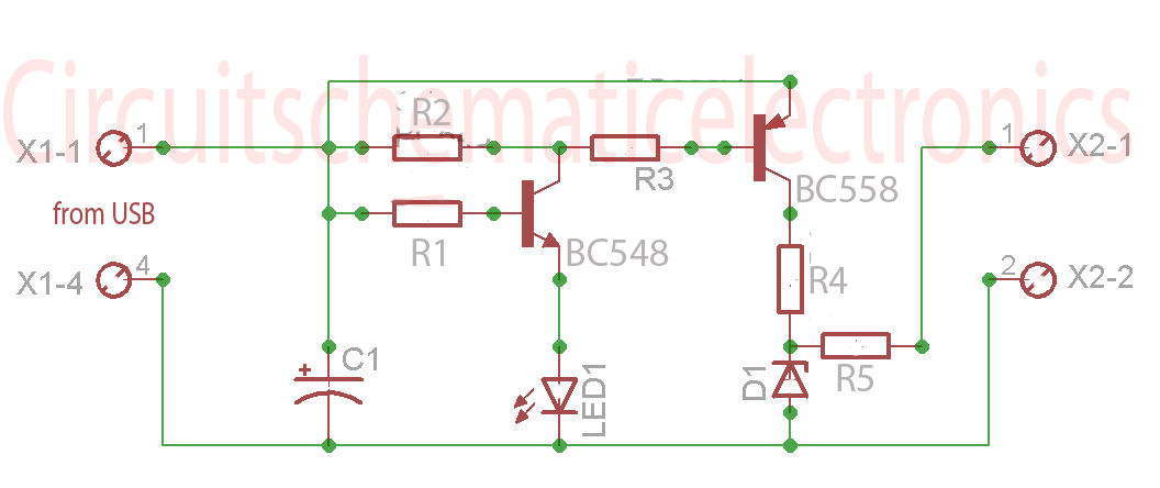
Without a USB to phone battery charger circuit, charging a phone battery using a USB port on a computer can quickly damage the battery, resulting in bulging. This occurs because the voltage output from USB is 5 volts, while...
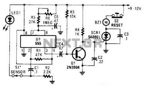
The alarm circuit utilizes a single 555 oscillator/timer (U1) that functions in both the alarm-trigger circuit and the entry-delay circuit. In this configuration, the trigger input of U1 at pin 2 is maintained in a high state through resistor...
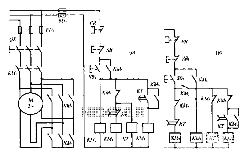
A star-delta switch is utilized for starting circuits, commonly depicted in Figure I-5 (a) of the knife wiring. While this method is effective, it poses security risks. When the motor starts, it can create significant voltage fluctuations that may...

A, B, and C are used for a large power split-phase system. The A + BC range generator phase line features an A-A indole path string containing two 220V/15W bulbs. The bulbs recover based on macro instructions from J...